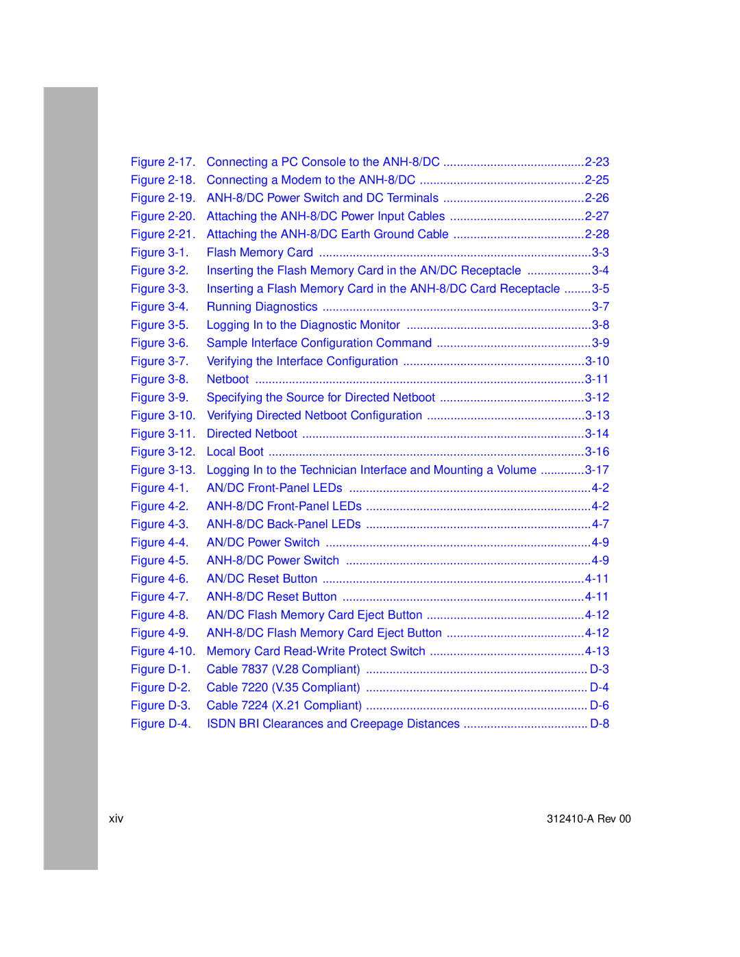
Figure | Connecting a PC Console to the | |
Figure | Connecting a Modem to the | |
Figure | ||
Figure | Attaching the | |
Figure | Attaching the | |
Figure | Flash Memory Card | |
Figure | Inserting the Flash Memory Card in the AN/DC Receptacle | |
Figure | Inserting a Flash Memory Card in the | |
Figure | Running Diagnostics | |
Figure | Logging In to the Diagnostic Monitor | |
Figure | Sample Interface Configuration Command | |
Figure | Verifying the Interface Configuration | |
Figure | Netboot | |
Figure | Specifying the Source for Directed Netboot | |
Figure | ||
Figure | Directed Netboot | |
Figure | Local Boot | |
Figure | Logging In to the Technician Interface and Mounting a Volume | |
Figure | AN/DC | |
Figure | ||
Figure | ||
Figure | AN/DC Power Switch | |
Figure | ||
Figure | AN/DC Reset Button | |
Figure | ||
Figure | AN/DC Flash Memory Card Eject Button | |
Figure | ||
Figure | Memory Card | |
Figure | Cable 7837 (V.28 Compliant) | |
Figure | Cable 7220 (V.35 Compliant) | |
Figure | Cable 7224 (X.21 Compliant) | |
Figure | ISDN BRI Clearances and Creepage Distances | |
xiv |
