Operating Instructions
Ricoh Corporation Calling for Service
Ricoh Laser AP2000
Means Power ON. b means Power OFF
Savin SLP20
Means Power ON. b means Power OFF
Page
Means Power ON. b means Power OFF
Trademarks
Safety During Operation
Safety Information
Iii
Page
Specifications
Low-power mode Energy Saver mode
Energy Star Program
Recycled Paper
Operating Instructions
Quick Installation Guide
Manuals for Your Printer
Manuals for Your Printer
Symbols
How to Read this Manual
Viii
Table of Contents
Uninstalling the Font Manager
Installing the PostScript Printer Driver
Uninstalling the PostScript Printer Driver
Installing the Font Manager
Specifications 143
Replacing the Toner Cartridge 114 Cleaning the Printer 117
Maintenance Menu 137
Interpreting the Configuration 139
Xii
150
Getting Acquainted
Features of Your Printer
Type 1 Printer
Guide to the Printer
Type 1 Printer Exterior
Type 1 Printer Interior
Transfer Roller
Fusing Unit Lock Levers brown
Fusing Unit
Pressure Release Levers blue
Type 2 Printer Exterior
Type 2 Printer
Type 2 Printer Interior
Power Switch Parallel Interface Connector
Power Error Data
Panel Display On Line indicator
Operation Panel
Form Feed key
Job Reset key
Keys
Escape key
Enter key
Menu key
Getting Acquainted
Option List
Installing Options
For Type 1 Printer
Available Options
For Type 2 Printer
Type 1 Printer Installing the Paper Feed Unit DLT Type
Type 1 Printer Installing Options
Type 1 Printer Installing the Paper Feed Unit LT Type
Type 1 Printer Installing the Network Interface Board Type
Type 1 Printer Installing Envelope Feeder Type
CD-ROM
Type 1 Printer Installing the Memory Unit Simm
Attach the back plate to its origi- nal position
Type 2 Printer Installing the Paper Feed Unit Type
Type 2 Printer Installing Options
Remove the red protective sheet taped on the guide
Then pull it out of the printer. Place it on a flat surface
Into the printer. Then slide it into
Type 2 Printer Installing the Network Interface Board Type
While lifting the front side
Envelope feeder, place the feeder
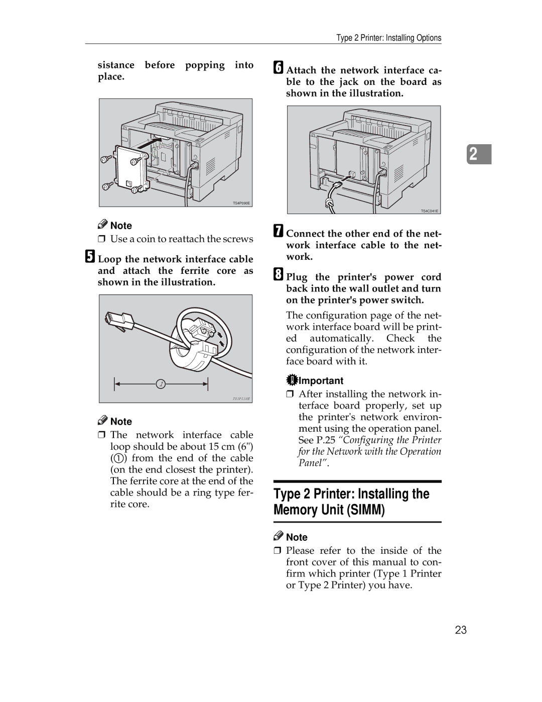
Sistance before popping into place
Type 2 Printer Installing the Memory Unit Simm
Turn on the printers power switch
Configuring the Printer for the Network with Operation Panel
Press Enter
Setting Up the IP Parameters
Press Menu
Press TU until the following message appears
Register the IP address you speci- fied
Turn the printers power switch off and on
Press On Line
Page
PostScript Printer Description PPD files for Windows
Printer Drivers for Your Printer
Printer Drivers for Your Printer
PCL printer drivers
PostScript Printer Description PPD files for Macintosh
Installing the printer driver
Installing the PCL 6/5e Printer Driver
Installing the PCL 6/5e Printer Driver
Windows 95/98 Installing the PCL 6/5e Printer Driver
Setting up options
Windows 3.1x Installing the PCL 6/5e Printer Driver
On the General tab, click Print Test
Setting up options
Click Close to close the Printers dialog
Windows NT4.0 Installing the PCL 6/5e Printer Driver
Printers windows appears
Windows 95/98 Uninstalling the PCL 6/5e Printer Driver
Uninstalling the PCL 6/5e Printer Driver
Windows 3.1x Uninstalling the PCL 6/5e Printer Driver
Windows NT4.0 Uninstalling the PCL 6/5e Printer Driver
Installing the PCL 6/5e Printer Driver
Installing the PostScript Printer Driver
Installing the PostScript Printer Driver
Windows 95/98 Installing the PostScript Printer Driver
\WINDOWS\SYSTEM\OPTION\CABS \WINDOWS\OPTION\CABS
Click the Device Options tab
Windows NT4.0 Installing the PostScript Printer Driver
Double-click the Add Printers icon
Dialog for installing the driver from a disk appears
Setting up options
Double-click the CD-ROM icon
Macintosh Installing the PPD File
Installing the PPD File
Click Device Settings tab
Click the LaserWriter 8 icon
Setting up the PPD file
Click Configure
On the Apple menu, select Chooser
Close the Chooser dialog
Windows 95/98 Uninstalling the PostScript Printer Driver
Uninstalling the PostScript Printer Driver
Windows NT4.0 Uninstalling the PostScript Printer Driver
Installing the PostScript Printer Driver
Windows 3.1x Installing the Font Manager
Installing the Font Manager
Installing the Font Manager
Windows 95/98 Installing the Font Manager
Windows NT4.0 Installing the Font Manager
Windows NT4.0 Uninstalling the Font Manager
Uninstalling the Font Manager
Windows 95/98 Uninstalling the Font Manager
Windows 3.1x Uninstalling the Font Manager
Follow the instructions on the screen
Making printer settings for a specific application
PCL 6/5e Accessing the Printer Properties
Windows 95/98 Accessing the Printer Properties
Making printer default settings
Windows 3.1x Accessing the Printer Setting Dialog
Printer group, select the printer you want to use
Windows NT4.0 Accessing the Printer Properties
Making printer default settings Printer Properties
On the File menu, click Print Setup
On the File menu, click Document Defaults
Making printer default settings Default Document Properties
PostScript Setting Up for Printing
Windows NT4.0 Accessing the Printer Properties
Making paper settings from an application
Macintosh Setting Up for Printing
LaserWriter 8 Page Setup dialog opens
After all the settings are the way you want, click OK
Setting up for printing from an application
Windows 95/98 Canceling Print Job
Canceling a Print Job
Windows 3.1x Canceling a Print Job
Click Close to close the dialog Press the printers Job Reset
Windows NT4.0 Canceling a Print Job
Canceling a Print Job
Printing a Document
Type 1 Printer
Paper and Other Media
Paper and Other Media Supported by Your Printer
Paper Types and Sizes
B6 JIS
Type 1 Printer Paper Sizes Metric version
Paper and Other Media Supported by Your Printer
Type 1 Printer Paper Sizes Inch version
Paper and Other Media Supported by Your Printer
Type 2 Printer
Paper weight and number of sheets to be set
Type 2 Printer Paper Sizes Metric version
Type 2 Printer Paper Sizes Inch version
Envelope Feeder Type 1400 *2
Paper types and cautions Plain paper
Precautions for Paper
Envelopes
OHP transparencies
Translucent paper
Adhesive labels
Metric version Inch version
Paper not supported by this printer
Printable Area
Slide the catches inwards to unlock the re-size tray
Type 1 Printer Loading Paper and Other Media
Pull the re-size tray until it stops
Load paper into the tray with the print side up
Return the catches to their orig- inal positions
Open the bypass tray
Adjust the side guides to the pa- per width
Type 1 Printer Loading Paper in the Bypass Tray
Until it stops
Start the print operation with your computer
Press T twice
Load paper into the paper tray with the print side up
Load envelopes until it stops, with the print side down
Type 1 Printer Loading Envelopes
Type 1 printer loading envelopes onto the bypass tray
Er. Then slide it inside until it stops
Type 1 printer loading envelopes into the envelope feeder
Press Enter Press UT until the follow- ing message appears
Push the bottom plate down until it locks into place
Paper Size Tray
Type 2 Printer Loading Paper in the Standard Paper Tray
Type 2 Printer Loading Paper and Other Media
Insert the paper tray into the printer until it stops
Type 2 Printer Loading Paper in the Bypass Tray
Type 2 Printer Loading Paper in the Optional Paper Tray
TS4Y160E
Type 2 printer loading envelopes onto the bypass tray
Type 2 Printer Loading Envelopes
TS4Y311E
Type 2 printer loading envelopes into the envelope feeder
Paper Size j 2.Env. Feeder l
Paper and Other Media
Error & Status Messages on the Operation Panel
Troubleshooting
Troubleshooting
Tray. ⇒ P.130 Paper Input
100
Paper Input 2/2
101
Unit accidentally
102
Placing the Toner Cartridge
103
104
105
Printer Doesnt Print
Check the Print to the following port box to make
Terface cable
Network Connection
106
107
Other Printing Problems
Friction Pad
108
Tings with the Operation Panel
109
110
Removing Misfed Paper
Push the blue pressure release le- vers marked with a
111
Slide the paper tray back into the printer until it stops
Open the front cover by pulling Front cover release buttons
Close the front cover
112
Turn the printers power switch on
If you uninstall the fusing unit accidentally
113
114
Replacing the Toner Cartridge
Ing the cartridge with one hand as shown in the illustration
115
116
Cleaning the Friction Pad
Cleaning the Printer
117
118
Cleaning the Paper Feed Roller
Pull the paper tray out of the printer
Move the printer to the edge of a stable table or desk
119
120
Turn the printers power switch off
121
Move the printer to the place where it was installed. Insert
Paper tray into the printer until it stops
122
123
124
Menu Chart
Making Printer Settings with the Operation Panel
125
126
Accessing the Main Menu
Press Enter Search for the desired menu with U or T
Making Printer Settings with the Operation Panel
127
Search for the desired menu with U or T
128
Job Control Menu
Job Control Parameters
Paper Input 1/2
129
Tray 2 option
Paper Input 2/2
Bypass Tray
Tray1
131
Print Quality
132
System 1/2
PCL Menu
System 2/2
133
134
PS Menu
135
Symbol Set
Printer Lang. Printer Language
Network Setup
Host Interface Menu
Host Interface Parameters
137
Maintenance Menu
Maintenance Parameters
Maintenance
138
List Print Menu
List Print Parameters
List Print
Interpreting the Configuration
140
Host Interface Printer Lang. Printer Language
Ethernet
PostScript
Inch version
Appendix
Memory Capacity and Paper Size
Metric version
142
Moving and Transporting the Printer
Mainframe
Specifications
Noise Emission Sound Power Level
Paper Weight
Power Source
Power Consumption
Paper Output Capacity
Weight
Warm-up Time
Paper Capacity Type 1 Printer
Optional Equipment
Options
Memory
Network optional network interface board required
Network Interface Board Type Topology
Envelope Feeder Type Dimensions W×D×H
Paper Feed Unit Type Dimensions W×D×H
Envelope Size
Protocols
Interface Connector
Number of Pins
Access Time
149
Maintenance Kit
Consumables
Toner Cartridge
150
Index
151
152
Be sure to pull the tape horizontally
Quick Installation GUIDEG031-8617
Connectingthe Power Cord
Quick Installation GUIDEG032-8617
Installingthe Papertray
Maintenance KIT TYPE2000
UE USA G517-8600
Introduction
Copyright
How to Read this Manual
Table of Contents
Checking the Contents of the Box
What is the Maintenance Kit?
Replacement Parts
Replacing Parts
Preparing to Replace the Parts
Replacing the Friction Pad
Push the friction pad until it locks securely
Shown in the illustration
Replacing the Paper Feed Rollers
Open the transfer roller cover
Replacing the Transfer Roller
Then slide it in B as shown in the illustration
Replacing the Fusing Unit
Push the brown fusing unit lock levers
Align the new fusing unit with the mark on the printer A,
Printing the Test
Config. Press Enter Key
Index
UE USA G517
Maintenance KIT TYPE1400
UE USA G517-8620
Introduction
Copyright
How to Read this Manual
Table of Contents
⇒ P.7 Replacing the Fric
TS4M070E
Replacing Parts
Preparing to Replace the Parts
Pull the tray out of the printer
Holes of the paper tray as shown in the illustration
Replacing the Paper Feed Roller
TS4M160E
TS4M200E
TS4M250E
Make sure the following message appears on the panel display
Clearing the Maintenance Condition
Index
Network Interface Board Type2000
Trademarks
Page
Configuring NetWare
Preparing the Printer Powering Up the Printer
Configuring NetWare 4.x Bindery Emulation
Windows IP Peer-to-Peer Printing
NWSetup NetWare and Print Server Configuration Program
Installation in a Windows Environment
Windows Peer-to-Peer Printing
Running Telnet
Unix Printing
Network Interface Board 10BaseT/100BaseTX/STP Cables
Chapter Introduction
Whats in Your Package
Software
Hardware/NOS Requirements
Version
Protocol or NOS
Conventions Used in this Document
Preparing the Printer
Powering Up the Printer
Page
Chapter
Configure the MAP Program
Where to Place the MAP
How to Install MAP
Using the MAP Program
Web IP Browser
Page
Configuring NetWare
Chapter NetWare Configuration
Create Print Queues
Start Pconsole and Select File Server
Enter the Print Server Name
Assign Print Queues to the Printer
Configure the Print Server
Choose Remote Other/Unknown and press the Enter key
Installing the Print Server on Multiple File Servers
Set Up Notify Options for the Printer Optional
Confirm Bindery Context
Configuring NetWare 4.x Bindery Emulation
Primary File Server
Preferred File Servers
Select Maintenance/Selective Install from the menu
Configure in Bindery Mode with Pconsole
Available Options
Page
Create Print Server Object
Create Printer Object
Create Print Queue Object
Check Assignments
Set Up and Reset the Printer
Assign Printer Object
Assign Print Server Object
Select Setup NetWare under Protocols Click on Enable NetWare
Network Interface Board Configuration
Changing the File Server
Using the Novell Pconsole Utility
Changing Print Queues
Press Insert at the File Server/Queue/Priority screen
How to Set Up Notify
Using the NWSetup Program
NWSetup NetWare and Print Server Configuration Program
How To Install
How To Initiate NWSetup
Enable NetWare
Setup Novell NetWare
Print Server
Print Server Name
Print Server Password
Password Retype
Enable NDS Mode
Preferred NDS Tree
Enable Bindery Mode
Print Server Settings
Enable Printer
Users/Groups Notified
Queues Serviced by
Printer Name
Printer
Deleting a Queue
Add User/Delete User
First message
Configuring the Notify Settings
Delay in minutes for
User/Group name
Delay in minutes for repeat messages
Page
Introduction and Preparation
Windows IPX Peer-to-Peer Printing
Windows IP Peer-to-Peer Printing
Installation and Operation
Introduction and Preparation
Page
Choosing the Printer
Chapter AppleTalk Configuration
Page
Windows for Workgroups
Installation in a Windows Environment
Assigning IP Address with ARP
Installing TCP/IP
Setting up the Network Interface Board
Loading the lpr Spooler
Setting up IP and lpr Parameters
Assigning IP Address with Bootp Lite
Creating an lpr Queue on the Workstation
Microsoft Windows 95/98
Assigning IP Address with BOOTPL32
Windows NT Instructions
Setting up lpr on the Workstation
Assigning IP Address with ARP
This is optional
Dynamic Host Configuration Protocol
IP Peer to Peer Printing
Peer-To-Peer IP Setup
Add Printers for IP Peer To Peer Printing
Port Number
Unix Printing
IP Address
Name
Using Bootp
Configuring the IP Address on the Network Interface Board
Sm = subnet mask\ Gw = gateway address
Using rarp
040c800ff printfast
Using ping
Arp -s 192.9.200.200 040c800ff
2 lpd/lpr Printing
Running Telnet
Setting Up a BSD Remote Printer to Use lpd
Configuration Utility
Configure IP Parameters
Making Connection and Main Menu
Select Printer Languages
Print Server Setup Job Detected to be Action
PCL, PS, Ascii
Enable/Disable Network Protocols
Exit Telnet
Reset Unit
Restore Factory
Change Password
LED Patterns Printer Then the NIB Operating Condition
LED Status Indicator
Status Report
Resetting the Print Server to Factory Default
Troubleshooting Checklists
How to Diagnose Problems
File Server Checklist
Troubleshooting Network Hardware Connections
Troubleshooting NetWare Protocol
NetWare Checklist
Workstation to Network Interface Board Connection Checklist
Network Interface Board Configuration Checklist
Network Interface Board Loses Its File Server Connection
Troubleshooting AppleTalk Protocol
Unable to Print from a Different Context
Page
Specifications Network Interface Board
Pin Number Color Ethernet
10BaseT/100BaseTX/STP Cables
Supplement for Chapter
Type2000 Option
Quick Configuration Guide
Type2000 Option Quick Configuration Guide
Page
Copyright
Symbols
Features
Configuring the IP/IPX MAP Utility
Configuration Programs Accessing the Configuration Programs
NWSetupNetWare Print Server Configuration
PCONSOLENetWare Print Server Configuration
Unix Configuration
Manuals for this Machine
Network Interface Board Type 2000 Quick Configuration Guide
This Guides Role
Page
Getting ready for the Software Installation
IPX-Peer to Peer
Configuration Programs
Bootp Lite
NWSetup
Insert the CD-ROM in the CD-ROM drive
Accessing the Configuration Programs
Click on CD ROM Contents
Click on Installation/Configuration Programs
Getting ready for the Software Installation
Launch NWSetup
NetWare Configuration
NWSetupNetWare Print Server Configuration
Install NWSetup
Enable Bindery Mode
Print Server Password
Change Password
Enable NDS Mode
Creating and Adding the Print Queues
Enable Printer box
Queues Serviced by Printer
File Server Volume
Add a New User or Group
Delay in seconds for first message
Delay in seconds for repeat messages
Configure the Notify Settings
User/Group name
Click on OK to apply these settings
This is the name of the current user/group
Define the Print Server
PCONSOLENetWare Print Server Configuration
NetWare 3.x Configuration
Define the Print Queue
Select Remote/Other Unknown and press the Enter key
Define the Printer
Assign the Print Queue
Select the Type field and press the Enter key
Define Print Queue
NetWare 4.x Configuration
Select Yes and then press the Enter key to exit Pconsole
Press the Insert key
Click on Start on the Task bar
Configuring the IP/IPX MAP Utility
Point to MAP and select MAP Setup
Map Setup dialog appears
What is Windows 95/98 Peer to Peer Printing?
Windows 95/98 Configuration
Click on Browse to set a different directory
Installing Peer to Peer Printing IP
Click on Yes to continue installation
Click on Windows 95 and NT IP Peer to Peer Printing
Click on OK to complete the installation
For manual installation
Click on Finish to complete the installation
Installing Peer to Peer Printing IPX
Click on Windows 95 and NT IPX Peer to Peer Printing
Installing Peer to Peer Printing IPX
Select the Printer Port
Dhcp
Dynamic Host Configuration Protocol
Dynamic Host Configuration Protocol Dhcp
Windows NT Configuration
Windows NT Configuration
TCP/IP Required Components
Select the Services tab
Windows NT4.0
Click on Go to send the new settings to the NIB
NIB TCP/IP Configuration
Windows NT Configuration
Setting Up LPR Printing
Windows 95/98
Selecting a Shared Printer
Windows NT4.0
At the Unix command prompt
Unix Configuration
Unix Configuration
Setting the IP Address
At the Unix command prompt, type ping desiredIPaddress
Setting Other TCP/IP Parameters
Browser, connect to http//NIBIPaddress
Unix Configuration
Pconsole
Page
A919