I/O parameters
Logic I/O
Code |
|
|
|
|
|
|
| Description |
| ||
|
|
|
|
|
|
|
|
|
|
| |
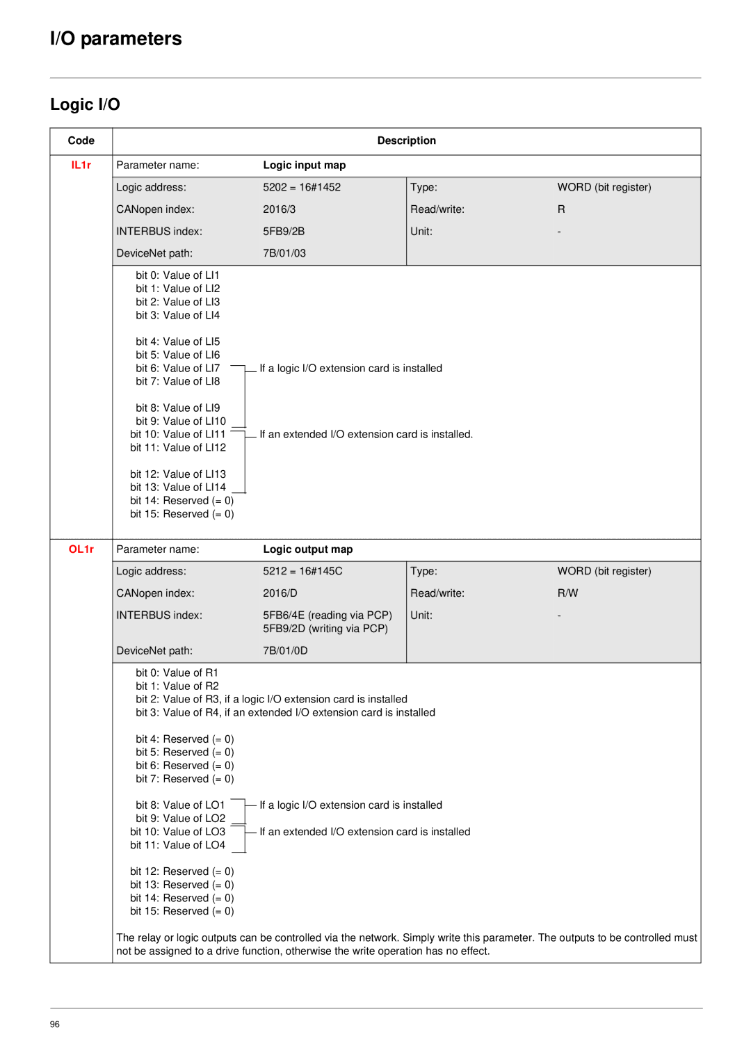
IL1r | Parameter name: |
|
|
|
|
|
| Logic input map |
|
| |
|
|
|
|
|
|
|
|
|
|
|
|
| Logic address: |
|
|
|
|
|
| 5202 = 16#1452 |
| Type: | WORD (bit register) |
| CANopen index: |
|
|
|
|
|
| 2016/3 |
| Read/write: | R |
| INTERBUS index: |
|
|
|
|
|
| 5FB9/2B |
| Unit: | - |
| DeviceNet path: |
|
|
|
|
|
| 7B/01/03 |
|
|
|
|
|
|
|
|
|
|
|
|
|
|
|
| bit 0: Value of | LI1 |
|
|
|
| |||||
| bit 1: Value of | LI2 |
|
|
|
| |||||
| bit 2: Value of | LI3 |
|
|
|
| |||||
| bit 3: Value of | LI4 |
|
|
|
| |||||
| bit 4: Value of | LI5 |
|
|
|
| |||||
| bit 5: Value of | LI6 |
|
|
|
| |||||
| bit 6: Value of | LI7 |
|
|
|
|
| If a logic I/O extension card is installed |
| ||
|
|
|
| ||||||||
| bit 7: Value of | LI8 |
|
|
|
|
|
|
| ||
| bit 8: Value of | LI9 |
|
|
|
|
|
|
| ||
| bit 9: Value of | LI10 |
|
|
|
|
|
|
| ||
| bit 10: Value of | LI11 |
|
|
|
|
| If an extended I/O extension card is installed. |
| ||
|
|
|
|
|
|
| |||||
|
|
|
|
|
|
| |||||
| bit 11: Value of | LI12 |
|
|
|
|
| ||||
| bit 12: Value of | LI13 |
|
|
|
|
| ||||
| bit 13: Value of LI14 |
|
|
|
|
|
|
| |||
| bit 14: Reserved (= 0) |
|
|
|
|
| |||||
| bit 15: Reserved (= 0) |
|
|
|
| ||||||
|
|
|
|
|
|
|
|
|
|
| |
OL1r | Parameter name: |
|
|
|
|
|
| Logic output map |
|
| |
|
|
|
|
|
|
|
|
|
|
|
|
| Logic address: |
|
|
|
|
|
| 5212 = 16#145C |
| Type: | WORD (bit register) |
| CANopen index: |
|
|
|
|
|
| 2016/D |
| Read/write: | R/W |
| INTERBUS index: |
|
|
|
|
|
| 5FB6/4E (reading via PCP) |
| Unit: | - |
|
|
|
|
|
|
|
| 5FB9/2D (writing via PCP) |
|
|
|
| DeviceNet path: |
|
|
|
|
|
| 7B/01/0D |
|
|
|
|
|
|
|
|
|
|
|
|
|
| |
| bit 0: Value of R1 |
|
|
|
| ||||||
| bit 1: Value of R2 |
|
|
|
| ||||||
| bit 2: Value of R3, if a logic I/O extension card is installed |
|
| ||||||||
| bit 3: Value of R4, if an extended I/O extension card is installed |
| |||||||||
| bit 4: Reserved (= 0) |
|
|
|
| ||||||
| bit 5: Reserved (= 0) |
|
|
|
| ||||||
| bit 6: Reserved (= 0) |
|
|
|
| ||||||
| bit 7: Reserved (= 0) |
|
|
|
| ||||||
| bit 8: Value of LO1 |
|
| If a logic I/O extension card is installed |
| ||||||
|
|
| |||||||||
|
|
|
|
|
|
| |||||
| bit 9: Value of LO2 |
|
|
|
|
|
|
| |||
| bit 10: Value of LO3 |
|
| If an extended I/O extension card is installed |
| ||||||
|
|
|
|
|
|
| |||||
| bit 11: Value of LO4 |
|
|
|
|
|
|
| |||
| bit 12: Reserved (= 0) |
|
|
|
| ||||||
| bit 13: Reserved (= 0) |
|
|
|
| ||||||
| bit 14: Reserved (= 0) |
|
|
|
| ||||||
| bit 15: Reserved (= 0) |
|
|
|
| ||||||
| The relay or logic outputs can be controlled via the network. Simply write this parameter. The outputs to be controlled must | ||||||||||
| not be assigned to a drive function, otherwise the write operation has no effect. |
| |||||||||
|
|
|
|
|
|
|
|
|
|
|
|
96