Status parameters
Code |
| Description |
| ||
|
|
|
|
| |
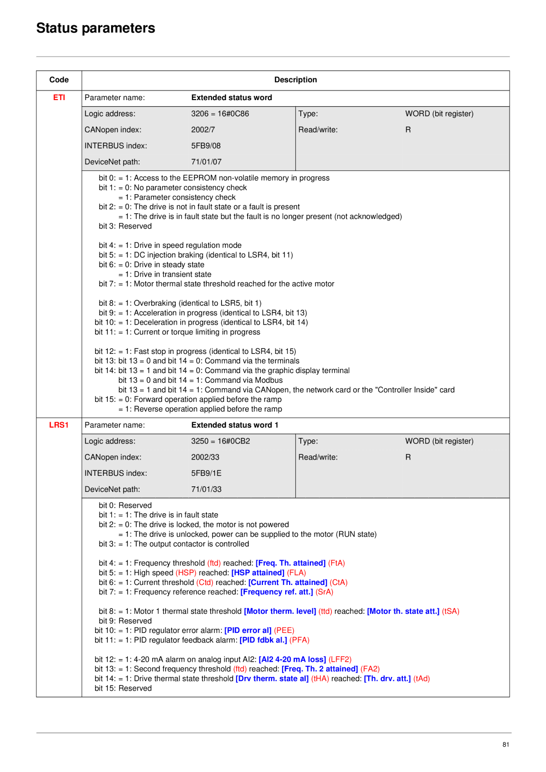
ETI | Parameter name: | Extended status word |
|
| |
|
|
|
|
|
|
| Logic address: | 3206 = 16#0C86 |
| Type: | WORD (bit register) |
| CANopen index: | 2002/7 |
| Read/write: | R |
| INTERBUS index: | 5FB9/08 |
|
|
|
| DeviceNet path: | 71/01/07 |
|
|
|
|
|
|
|
| |
| bit 0: = 1: Access to the EEPROM |
| |||
| bit 1: = 0: No parameter consistency check |
|
| ||
| = 1: Parameter consistency check |
|
| ||
| bit 2: = 0: The drive is not in fault state or a fault is present |
| |||
| = 1: The drive is in fault state but the fault is no longer present (not acknowledged) |
| |||
| bit 3: Reserved |
|
|
|
|
| bit 4: = 1: Drive in speed regulation mode |
|
| ||
| bit 5: = 1: DC injection braking (identical to LSR4, bit 11) |
|
| ||
| bit 6: = 0: Drive in steady state |
|
| ||
| = 1: Drive in transient state |
|
| ||
| bit 7: = 1: Motor thermal state threshold reached for the active motor |
| |||
| bit 8: = 1: Overbraking (identical to LSR5, bit 1) |
|
| ||
| bit 9: = 1: Acceleration in progress (identical to LSR4, bit 13) |
| |||
| bit 10: = 1: Deceleration in progress (identical to LSR4, bit 14) |
| |||
| bit 11: = 1: Current or torque limiting in progress |
|
| ||
| bit 12: = 1: Fast stop in progress (identical to LSR4, bit 15) |
|
| ||
| bit 13: bit 13 = 0 and bit 14 = 0: Command via the terminals |
| |||
| bit 14: bit 13 = 1 and bit 14 = 0: Command via the graphic display terminal |
| |||
| bit 13 = 0 and bit 14 = 1: Command via Modbus |
|
| ||
| bit 13 = 1 and bit 14 = 1: Command via CANopen, the network card or the "Controller Inside" card | ||||
| bit 15: = 0: Forward operation applied before the ramp |
|
| ||
| = 1: Reverse operation applied before the ramp |
|
| ||
|
|
|
|
| |
LRS1 | Parameter name: | Extended status word 1 |
|
| |
|
|
|
|
|
|
| Logic address: | 3250 = 16#0CB2 |
| Type: | WORD (bit register) |
| CANopen index: | 2002/33 |
| Read/write: | R |
| INTERBUS index: | 5FB9/1E |
|
|
|
| DeviceNet path: | 71/01/33 |
|
|
|
|
|
|
|
|
|
| bit 0: Reserved |
|
|
|
|
| bit 1: = 1: The drive is in fault state |
|
| ||
| bit 2: = 0: The drive is locked, the motor is not powered |
|
| ||
| = 1: The drive is unlocked, power can be supplied to the motor (RUN state) |
| |||
| bit 3: = 1: The output contactor is controlled |
|
| ||
| bit 4: = 1: Frequency threshold (ftd) reached: [Freq. Th. attained] (FtA) |
| |||
| bit 5: = 1: High speed (HSP) reached: [HSP attained] (FLA) |
| |||
| bit 6: = 1: Current threshold (Ctd) reached: [Current Th. attained] (CtA) |
| |||
| bit 7: = 1: Frequency reference reached: [Frequency ref. att.] (SrA) |
| |||
| bit 8: = 1: Motor 1 thermal state threshold [Motor therm. level] (ttd) reached: [Motor th. state att.] (tSA) | ||||
| bit 9: Reserved |
|
|
|
|
| bit 10: = 1: PID regulator error alarm: [PID error al] (PEE) |
|
| ||
| bit 11: = 1: PID regulator feedback alarm: [PID fdbk al.] (PFA) |
| |||
| bit 12: = 1: |
| |||
| bit 13: = 1: Second frequency threshold (ftd) reached: [Freq. Th. 2 attained] (FA2) |
| |||
| bit 14: = 1: Drive thermal state threshold [Drv therm. state al] (tHA) reached: [Th. drv. att.] (tAd) | ||||
| bit 15: Reserved |
|
|
|
|
|
|
|
|
|
|
81