Status parameters
Code |
|
| Description |
| |
|
|
|
|
| |
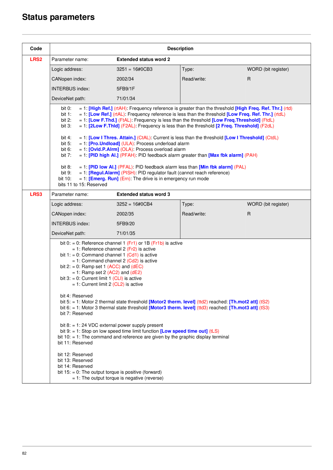
LRS2 | Parameter name: | Extended status word 2 |
|
| |
|
|
|
|
| |
| Logic address: | 3251 = 16#0CB3 | Type: | WORD (bit register) | |
| CANopen index: | 2002/34 | Read/write: | R | |
| INTERBUS index: | 5FB9/1F |
|
| |
| DeviceNet path: | 71/01/34 |
|
| |
|
|
|
|
| |
| bit 0: | = 1: [High Ref.] (rtAH): Frequency reference is greater than the threshold [High Freq. Ref. Thr.] (rtd) | |||
| bit 1: | = 1: [Low Ref.] (rtAL): Frequency reference is less than the threshold [Low Freq. Ref. Thr.] (rtdL) | |||
| bit 2: | = 1: [Low F.Thd.] (FtAL): Frequency is less than the threshold [Low Freq.Threshold] (FtdL) | |||
| bit 3: = 1: [2Low F.Thld] (F2AL): Frequency is less than the threshold [2 Freq. Threshold] (F2dL) | ||||
| bit 4: | = 1: [Low I Thres. Attain.] (CtAL): Current is less than the threshold [Low I Threshold] (CtdL) | |||
| bit 5: | = 1: [Pro.Undload] (ULA): Process underload alarm |
| ||
| bit 6: | = 1: [Ovld.P.Alrm] (OLA): Process overload alarm |
| ||
| bit 7: | = 1: [PID high Al.] (PFAH): PID feedback alarm greater than [Max fbk alarm] (PAH) | |||
| bit 8: | = 1: [PID low Al.] (PFAL): PID feedback alarm less than [Min fbk alarm] (PAL) |
| ||
| bit 9: | = 1: [Regul.Alarm] (PISH): PID regulator fault (cannot reach reference) |
| ||
| bit 10: | = 1: [Emerg. Run] (Ern): The drive is in emergency run mode |
| ||
| bits 11 to 15: Reserved |
|
|
| |
|
|
|
|
| |
LRS3 | Parameter name: | Extended status word 3 |
|
| |
|
|
|
|
| |
| Logic address: | 3252 = 16#0CB4 | Type: | WORD (bit register) | |
| CANopen index: | 2002/35 | Read/write: | R | |
| INTERBUS index: | 5FB9/20 |
|
| |
| DeviceNet path: | 71/01/35 |
|
| |
|
|
|
|
| |
| bit 0: = 0: Reference channel 1 (Fr1) or 1B (Fr1b) is active |
| |||
|
| = 1: Reference channel 2 (Fr2) is active |
|
| |
| bit 1: = 0: Command channel 1 (Cd1) is active |
|
| ||
|
| = 1: Command channel 2 (Cd2) is active |
|
| |
| bit 2: = 0: Ramp set 1 (ACC) and (dEC) |
|
| ||
|
| = 1: Ramp set 2 (AC2) and (dE2) |
|
| |
| bit 3: = 0: Current limit 1 (CLI) is active |
|
| ||
|
| = 1: Current limit 2 (CL2) is active |
|
| |
| bit 4: Reserved |
|
|
| |
| bit 5: = 1: Motor 2 thermal state threshold [Motor2 therm. level] (ttd2) reached: [Th.mot2 att] (tS2) | ||||
| bit 6: = 1: Motor 3 thermal state threshold [Motor3 therm. level] (ttd3) reached: [Th.mot3 att] (tS3) | ||||
| bit 7: Reserved |
|
|
| |
| bit 8: = 1: 24 VDC external power supply present |
|
| ||
| bit 9: = 1: Stop on low speed time limit function [Low speed time out] (tLS) |
| |||
| bit 10: = 1: The command and reference are given by the graphic display terminal |
| |||
| bit 11: Reserved |
|
|
| |
| bit 12: Reserved |
|
|
| |
| bit 13: Reserved |
|
|
| |
| bit 14: Reserved |
|
|
| |
| bit 15: = 0: The output torque is positive (forward) |
|
| ||
|
| = 1: The output torque is negative (reverse) |
|
| |
|
|
|
|
|
|
82