Status parameters
Code |
| Description |
| |
|
|
|
|
|
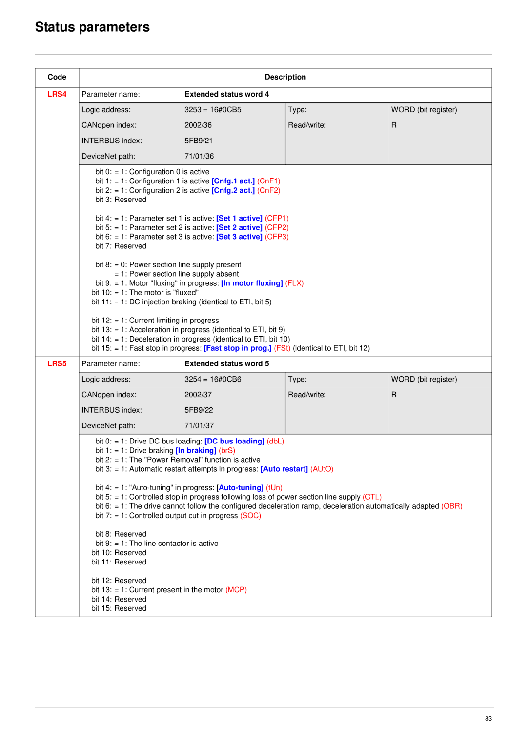
LRS4 | Parameter name: | Extended status word 4 |
|
|
|
|
|
|
|
| Logic address: | 3253 = 16#0CB5 | Type: | WORD (bit register) |
| CANopen index: | 2002/36 | Read/write: | R |
| INTERBUS index: | 5FB9/21 |
|
|
| DeviceNet path: | 71/01/36 |
|
|
|
|
|
|
|
| bit 0: = 1: Configuration 0 is active |
|
| |
| bit 1: = 1: Configuration 1 is active [Cnfg.1 act.] (CnF1) |
|
| |
| bit 2: = 1: Configuration 2 is active [Cnfg.2 act.] (CnF2) |
|
| |
| bit 3: Reserved |
|
|
|
| bit 4: = 1: Parameter set 1 is active: [Set 1 active] (CFP1) |
| ||
| bit 5: = 1: Parameter set 2 is active: [Set 2 active] (CFP2) |
| ||
| bit 6: = 1: Parameter set 3 is active: [Set 3 active] (CFP3) |
| ||
| bit 7: Reserved |
|
|
|
| bit 8: = 0: Power section line supply present |
|
| |
| = 1: Power section line supply absent |
|
| |
| bit 9: = 1: Motor "fluxing" in progress: [In motor fluxing] (FLX) |
| ||
| bit 10: = 1: The motor is "fluxed" |
|
| |
| bit 11: = 1: DC injection braking (identical to ETI, bit 5) |
|
| |
| bit 12: = 1: Current limiting in progress |
|
| |
| bit 13: = 1: Acceleration in progress (identical to ETI, bit 9) |
|
| |
| bit 14: = 1: Deceleration in progress (identical to ETI, bit 10) |
| ||
| bit 15: = 1: Fast stop in progress: [Fast stop in prog.] (FSt) (identical to ETI, bit 12) |
| ||
|
|
|
|
|
LRS5 | Parameter name: | Extended status word 5 |
|
|
|
|
|
|
|
| Logic address: | 3254 = 16#0CB6 | Type: | WORD (bit register) |
| CANopen index: | 2002/37 | Read/write: | R |
| INTERBUS index: | 5FB9/22 |
|
|
| DeviceNet path: | 71/01/37 |
|
|
|
|
|
|
|
| bit 0: = 1: Drive DC bus loading: [DC bus loading] (dbL) |
|
| |
| bit 1: = 1: Drive braking [In braking] (brS) |
|
| |
| bit 2: = 1: The "Power Removal" function is active |
|
| |
| bit 3: = 1: Automatic restart attempts in progress: [Auto restart] (AUtO) |
| ||
| bit 4: = 1: |
|
| |
| bit 5: = 1: Controlled stop in progress following loss of power section line supply (CTL) |
| ||
| bit 6: = 1: The drive cannot follow the configured deceleration ramp, deceleration automatically adapted (OBR) | |||
| bit 7: = 1: Controlled output cut in progress (SOC) |
|
| |
| bit 8: Reserved |
|
|
|
| bit 9: = 1: The line contactor is active |
|
| |
| bit 10: Reserved |
|
|
|
| bit 11: Reserved |
|
|
|
| bit 12: Reserved |
|
|
|
| bit 13: = 1: Current present in the motor (MCP) |
|
| |
| bit 14: Reserved |
|
|
|
| bit 15: Reserved |
|
|
|
|
|
|
|
|
83
