Command/reference switching
Reference switching principle
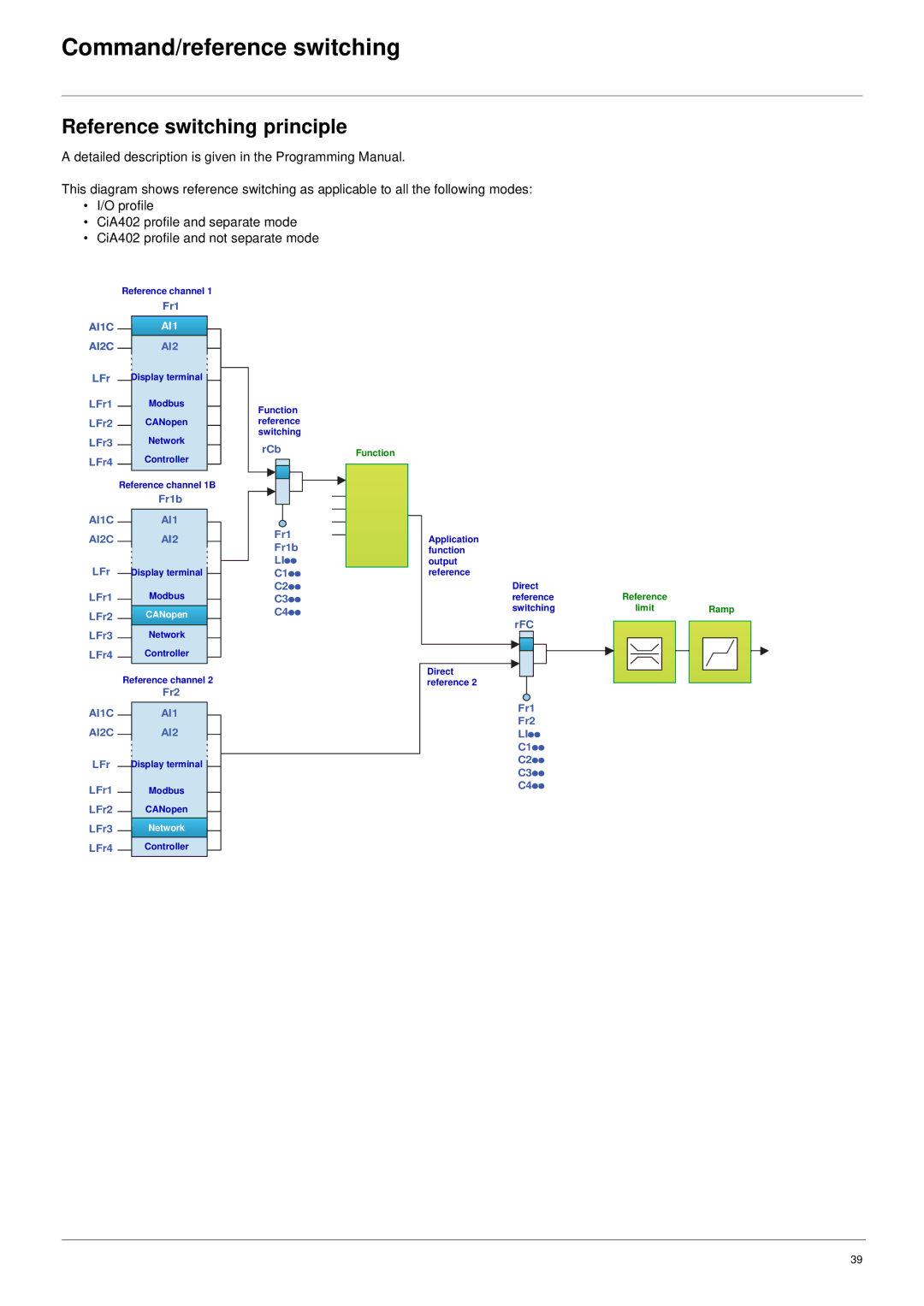
A detailed description is given in the Programming Manual.
This diagram shows reference switching as applicable to all the following modes:
•I/O profile
•CiA402 profile and separate mode
•CiA402 profile and not separate mode
Reference channel 1
|
| Fr1 |
| |
AI1C |
| AI1 |
|
|
AI2C |
| AI2 |
|
|
|
|
| ||
LFr |
| Display terminal |
|
|
|
|
| ||
|
|
| ||
LFr1 |
| Modbus |
|
|
|
|
| ||
LFr2 |
| CANopen |
|
|
|
|
| ||
LFr3 |
| Network |
|
|
|
|
| ||
LFr4 |
| Controller |
|
|
|
|
| ||
| Reference channel 1B |
| ||
|
| Fr1b |
| |
|
|
|
|
|
AI1C |
| AI1 |
|
|
AI2C |
| AI2 |
|
|
|
|
| ||
LFr |
| Display terminal |
|
|
|
|
| ||
|
|
| ||
LFr1 |
| Modbus |
|
|
|
|
| ||
LFr2 |
| CANopen |
|
|
|
|
| ||
LFr3 |
| Network |
|
|
|
|
| ||
LFr4 |
| Controller |
|
|
|
|
| ||
| Reference channel 2 |
| ||
|
| Fr2 |
| |
AI1C |
| AI1 |
|
|
AI2C |
| AI2 |
|
|
|
|
| ||
LFr |
| Display terminal |
|
|
|
|
| ||
LFr1 |
| Modbus |
|
|
|
|
| ||
LFr2 |
| CANopen |
|
|
|
|
| ||
LFr3 |
| Network |
|
|
|
|
| ||
LFr4 |
| Controller |
|
|
|
|
| ||
Function reference switching
rCb
Fr1
Fr1b
LIpp
C1pp
C2pp
C3pp
C4pp
Function
Application function output reference
Direct | Reference |
|
reference |
| |
switching | limit | Ramp |
rFC
Direct reference 2
Fr1
Fr2
LIpp
C1pp
C2pp
C3pp
C4pp
39
