CiA402 profile
Status word (ETA)
bit 7 | bit 6 | bit 5 | bit 4 | |
|
|
|
| |
Warning | Switch on | Quick stop | Voltage | |
disabled | enabled | |||
|
| |||
|
|
|
| |
| Power section | Emergency | Power section | |
Alarm | line supply | line supply | ||
stop | ||||
| disabled | present | ||
|
| |||
|
|
|
| |
|
|
|
| |
bit 15 | bit 14 | bit 13 | bit 12 | |
|
|
|
| |
Direction of | Stop via | Reserved (= | Reserved (= | |
rotation | STOP key | 0) | 0) | |
|
|
|
|
bit 3 | bit 2 | bit 1 | bit 0 | |
|
|
|
| |
Fault | Operation | Switched on | Ready to | |
enabled | switch on | |||
|
| |||
|
|
|
| |
|
|
| Awaiting | |
Fault | Running | Ready | power section | |
|
|
| line supply | |
|
|
|
|
bit 11 | bit 10 | bit 9 | bit 8 |
|
|
|
|
Internal limit | Target | Remote |
|
active | reached |
| |
|
| ||
|
|
| Reserved (= 0) |
Reference | Reference | Command or | |
reference via |
| ||
outside limits | reached |
| |
network |
| ||
|
|
| |
|
|
|
|
|
| bit 6 | bit 5 | bit 4 | bit 3 | bit 2 | bit 1 | bit 0 |
| ETA | |
| Status | Switch on | Quick | Voltage | Fault | Operation | Switched | Ready to |
| masked by | |
|
| disabled | stop | enabled | enabled | on | switch on |
| 16#006F (1) | ||
1 | - Not ready to | 0 | x | x | 0 | 0 | 0 | 0 |
| - | |
| switch on |
| |||||||||
|
|
|
|
|
|
|
|
|
| ||
|
|
|
|
|
|
|
|
|
|
| |
2 | - Switch on | 1 | x | x | 0 | 0 | 0 | 0 |
| 16#0040 | |
| disabled |
| |||||||||
|
|
|
|
|
|
|
|
|
| ||
|
|
|
|
|
|
|
|
|
|
| |
3 | - Ready to | 0 | 1 | x | 0 | 0 | 0 | 1 |
| 16#0021 | |
| switch on |
| |||||||||
|
|
|
|
|
|
|
|
|
| ||
|
|
|
|
|
|
|
|
|
|
| |
4 | - Switched on | 0 | 1 | 1 | 0 | 0 | 1 | 1 |
| 16#0023 | |
|
|
|
|
|
|
|
|
|
|
| |
5 | - Operation | 0 | 1 | 1 | 0 | 1 | 1 | 1 |
| 16#0027 | |
| enabled |
| |||||||||
|
|
|
|
|
|
|
|
|
| ||
|
|
|
|
|
|
|
|
|
|
| |
6 | - Quick stop | 0 | 0 | 1 | 0 | 1 | 1 | 1 |
| 16#0007 | |
| active |
| |||||||||
|
|
|
|
|
|
|
|
|
| ||
|
|
|
|
|
|
|
|
|
| ||
7 - Fault reaction | 0 | x | x | 1 | 1 | 1 | 1 |
| - | ||
| active |
| |||||||||
|
|
|
|
|
|
|
|
|
| ||
|
|
|
|
|
|
|
|
|
|
| |
8 | - Fault | 0 | x | x | 1 | 0 | 0 | 0 |
| 16#0008 (2) | |
or | 16#0028 | ||||||||||
|
|
|
|
|
|
|
|
| |||
|
|
|
|
|
|
|
|
|
|
| |
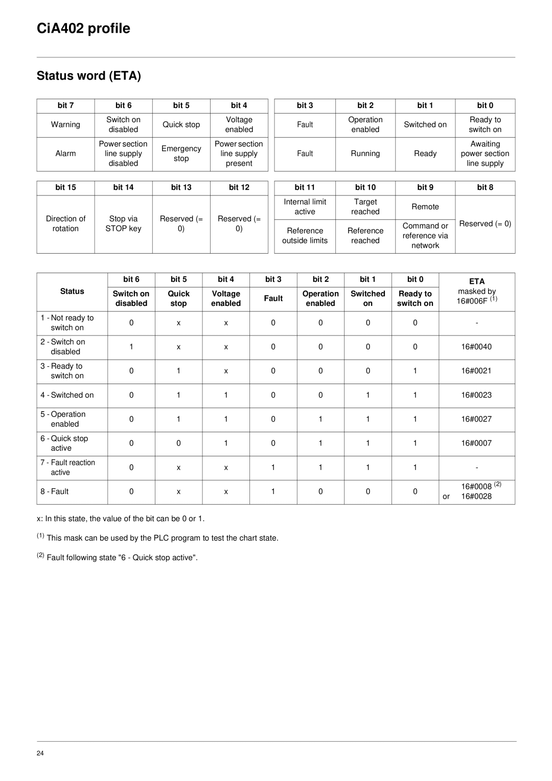
x: In this state, the value of the bit can be 0 or 1.
(1)This mask can be used by the PLC program to test the chart state.
(2)Fault following state "6 - Quick stop active".
24
