Main code | Sub code |
|
|
|
|
|
|
| Content | |
|
|
|
|
|
|
|
|
| ||
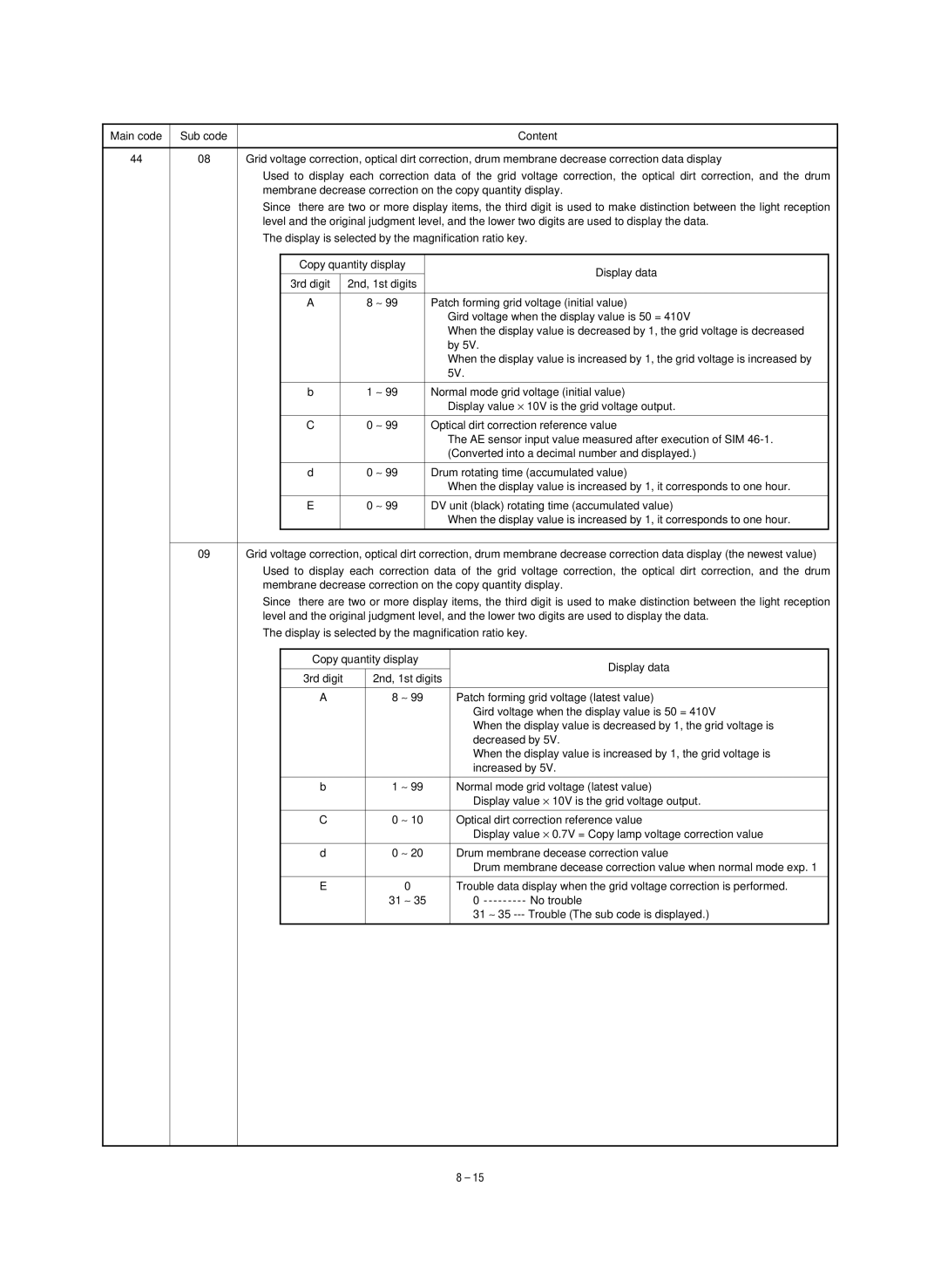
44 | 08 | Grid voltage correction, optical dirt correction, drum membrane decrease correction data display | ||||||||
|
| Used to display each correction data of the grid voltage correction, the optical dirt correction, and the drum | ||||||||
|
| membrane decrease correction on the copy quantity display. | ||||||||
|
| Since there are two or more display items, the third digit is used to make distinction between the light reception | ||||||||
|
| level and the original judgment level, and the lower two digits are used to display the data. | ||||||||
|
| The display is selected by the magnification ratio key. | ||||||||
|
|
|
|
|
|
|
| |||
|
|
| Copy quantity display |
|
| Display data |
| |||
|
|
|
|
|
|
|
|
|
| |
|
|
| 3rd digit |
| 2nd, 1st digits |
|
|
|
| |
|
|
|
|
|
|
|
|
|
|
|
|
|
| A |
|
| 8 ∼ 99 |
| Patch forming grid voltage (initial value) |
| |
|
|
|
|
|
|
|
| Gird voltage when the display value is 50 = 410V |
| |
|
|
|
|
|
|
|
| When the display value is decreased by 1, the grid voltage is decreased |
| |
|
|
|
|
|
|
|
| by 5V. |
| |
|
|
|
|
|
|
|
| When the display value is increased by 1, the grid voltage is increased by |
| |
|
|
|
|
|
|
|
| 5V. |
| |
|
|
|
|
|
|
|
|
|
|
|
|
|
| b |
|
| 1 ∼ 99 |
| Normal mode grid voltage (initial value) |
| |
|
|
|
|
|
|
|
| Display value × 10V is the grid voltage output. |
| |
|
|
|
|
|
|
|
|
|
|
|
|
|
| C |
|
| 0 ∼ 99 |
| Optical dirt correction reference value |
| |
|
|
|
|
|
|
|
| The AE sensor input value measured after execution of SIM |
| |
|
|
|
|
|
|
|
| (Converted into a decimal number and displayed.) |
| |
|
|
|
|
|
|
|
|
|
|
|
|
|
| d |
|
| 0 ∼ 99 |
| Drum rotating time (accumulated value) |
| |
|
|
|
|
|
|
|
| When the display value is increased by 1, it corresponds to one hour. |
| |
|
|
|
|
|
|
|
|
|
|
|
|
|
| E |
|
| 0 ∼ 99 |
| DV unit (black) rotating time (accumulated value) |
| |
|
|
|
|
|
|
|
| When the display value is increased by 1, it corresponds to one hour. |
| |
|
|
|
|
|
|
|
|
| ||
|
|
|
|
| ||||||
| 09 | Grid voltage correction, optical dirt correction, drum membrane decrease correction data display (the newest value) | ||||||||
|
| Used to display each correction data of the grid voltage correction, the optical dirt correction, and the drum | ||||||||
|
| membrane decrease correction on the copy quantity display. | ||||||||
|
| Since there are two or more display items, the third digit is used to make distinction between the light reception | ||||||||
|
| level and the original judgment level, and the lower two digits are used to display the data. | ||||||||
|
| The display is selected by the magnification ratio key. | ||||||||
|
|
|
|
|
|
| ||||
|
|
| Copy quantity display |
| Display data |
| ||||
|
|
|
|
|
|
|
|
|
| |
|
|
| 3rd digit |
| 2nd, 1st digits |
|
| |||
|
|
|
|
|
|
|
|
| ||
|
|
| A |
| 8 ∼ 99 |
| Patch forming grid voltage (latest value) |
| ||
|
|
|
|
|
|
|
|
| Gird voltage when the display value is 50 = 410V |
|
|
|
|
|
|
|
|
|
| When the display value is decreased by 1, the grid voltage is |
|
|
|
|
|
|
|
|
|
| decreased by 5V. |
|
|
|
|
|
|
|
|
|
| When the display value is increased by 1, the grid voltage is |
|
|
|
|
|
|
|
|
|
| increased by 5V. |
|
|
|
|
|
|
|
|
|
| ||
|
|
| b |
| 1 ∼ 99 |
| Normal mode grid voltage (latest value) |
| ||
|
|
|
|
|
|
|
|
| Display value × 10V is the grid voltage output. |
|
|
|
|
|
|
|
|
|
| ||
|
|
| C |
| 0 ∼ 10 |
| Optical dirt correction reference value |
| ||
|
|
|
|
|
|
|
|
| Display value × 0.7V = Copy lamp voltage correction value |
|
|
|
|
|
|
|
|
|
| ||
|
|
| d |
| 0 ∼ 20 |
| Drum membrane decease correction value |
| ||
|
|
|
|
|
|
|
|
| Drum membrane decease correction value when normal mode exp. 1 |
|
|
|
|
|
|
|
|
|
|
| |
|
|
| E |
| 0 |
|
| Trouble data display when the grid voltage correction is performed. |
| |
|
|
|
|
|
| 31 ∼ 35 |
| 0 |
| |
|
|
|
|
|
|
|
|
| 31 ∼ 35 |
|
|
|
|
|
|
|
|
|
|
|
|
|
|
|
|
|
|
|
|
|
|
|
8 – 15