4)Copy lamp unit installation (Mirror base A positioning)
This adjustment must be performed in the following cases:
•When the mirror base drive wire is replaced.
•When the mirror base A or B is replaced.
•When any part in the dark box is replaced.
When installing the mirror base, reverse the removal procedure of
1Put the mirror base A in the copier. Pass the mirror base drive wires in the front frame side and the rear frame side through the clearance between the mirror base A and the mirror base wire fixing plate. Do not tighten the mirror base A wire fixing screw at that time.
2Bring the mirror base B into contact with the positioning plate, put a flat jig (such as a scale edge) onto the right surface of the optical base plate (paper feed side), press the projection of the copy lamp unit onto the jig and fix it with two screws.
(Note) When tightening the copy lamp unit fixing screws, be sure to press the projection onto the scale.
Horizontal scales
Projections
5) No. 4/5 mirror unit (mirror base C) replacement
A. No. 4/5 mirror removal
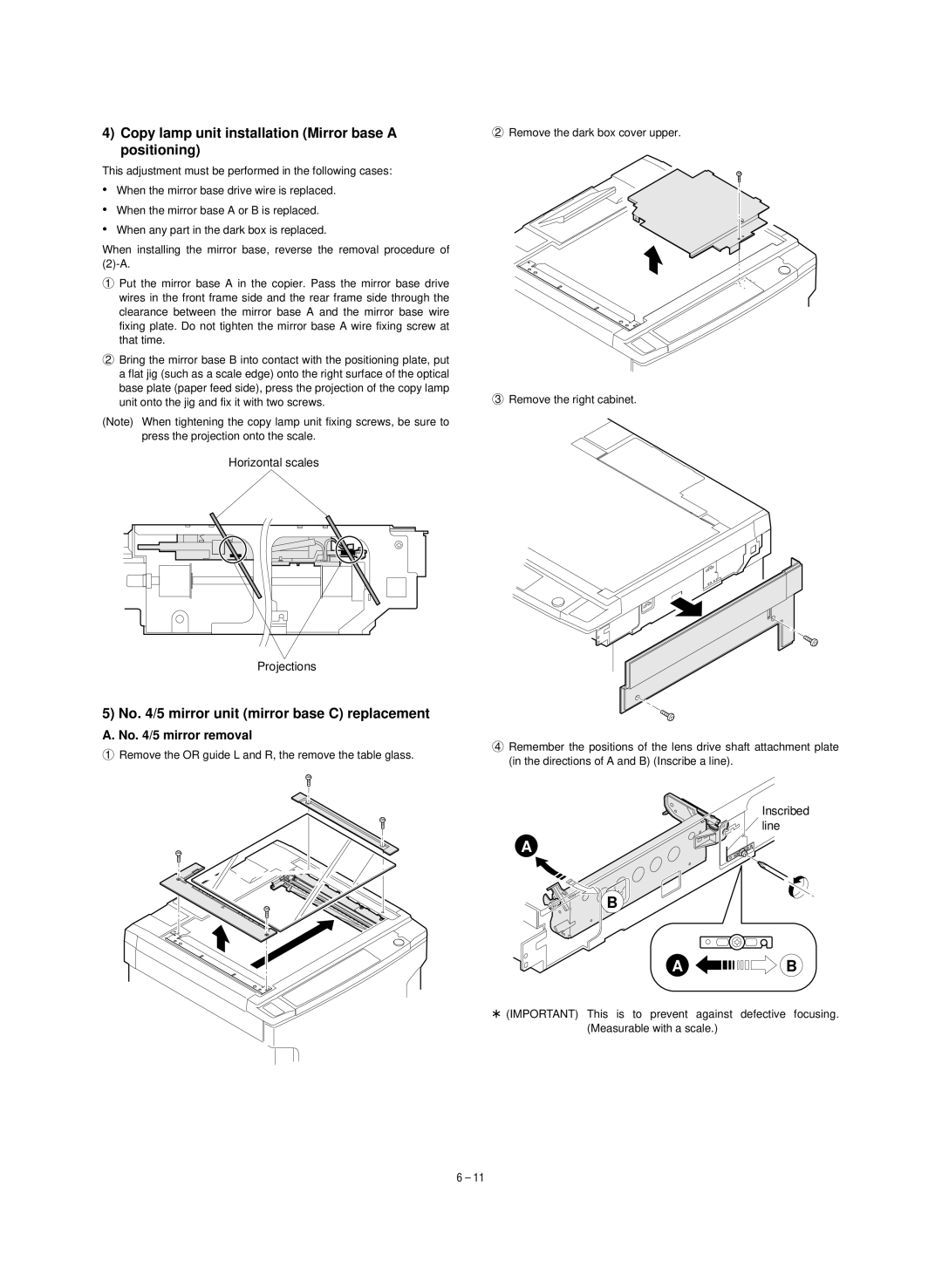
1Remove the OR guide L and R, the remove the table glass.
2Remove the dark box cover upper.
3Remove the right cabinet.
4Remember the positions of the lens drive shaft attachment plate (in the directions of A and B) (Inscribe a line).
Inscribed line
A
B
A ![]()
![]()
![]()
![]()
![]()
![]()
![]()
![]()
![]()
![]()
![]()
![]()
![]()
![]() B
B
*(IMPORTANT) This is to prevent against defective focusing. (Measurable with a scale.)
6 – 11