<Adjustment procedure>
(1)Make an original for adjustment.
Draw parallel lines at 10cm from the both edges of an A3 or 11" × 17" white paper. (Be careful to draw precisely parallel
lines.)
Parallel line | Parallel line |
10mm | 10mm |
10mm | 10mm |
Blank paper
(2)Set the adjustment original made in (1) as shown below.
Glass holding plate
Adjustment procedure (1)
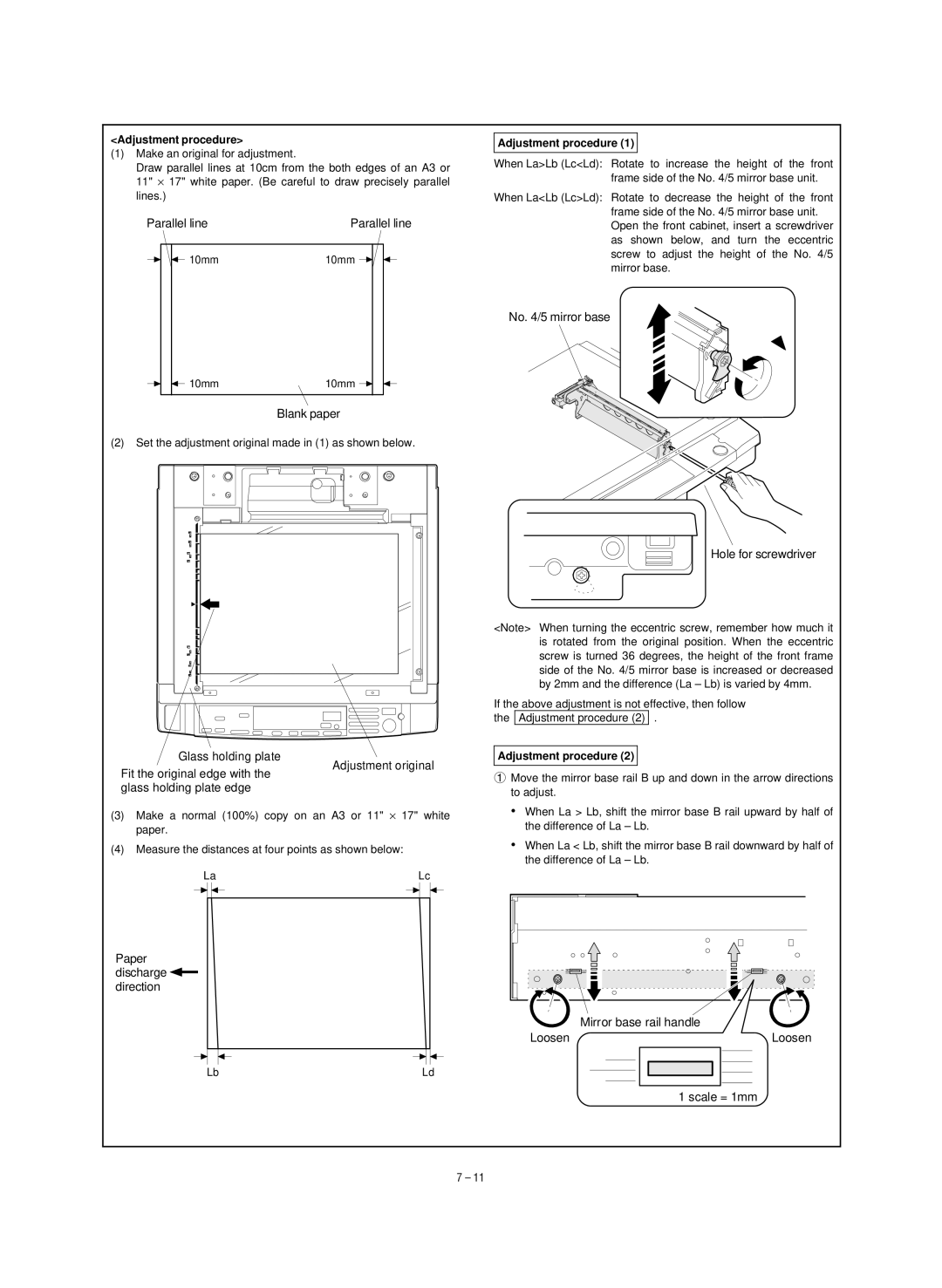
When La>Lb (Lc<Ld): Rotate to increase the height of the front frame side of the No. 4/5 mirror base unit.
When La<Lb (Lc>Ld): Rotate to decrease the height of the front frame side of the No. 4/5 mirror base unit. Open the front cabinet, insert a screwdriver as shown below, and turn the eccentric screw to adjust the height of the No. 4/5 mirror base.
No. 4/5 mirror base
Hole for screwdriver
<Note> When turning the eccentric screw, remember how much it is rotated from the original position. When the eccentric screw is turned 36 degrees, the height of the front frame side of the No. 4/5 mirror base is increased or decreased by 2mm and the difference (La – Lb) is varied by 4mm.
If the above adjustment is not effective, then follow the Adjustment procedure (2) .
Adjustment procedure (2)
Fit the original edge with the glass holding plate edge
Adjustment original
1 Move the mirror base rail B up and down in the arrow directions |
to adjust. |
(3)Make a normal (100%) copy on an A3 or 11" × 17" white paper.
(4)Measure the distances at four points as shown below:
La |
| Lc |
| |||
|
|
|
|
|
|
|
|
|
|
|
|
|
|
• | When La > Lb, shift the mirror base B rail upward by half of |
| the difference of La – Lb. |
• | When La < Lb, shift the mirror base B rail downward by half of |
| the difference of La – Lb. |
Paper discharge ![]()
![]() direction
direction
Mirror base rail handle
Loosen | Loosen |
Lb | Ld |
1 scale = 1mm
7 – 11