2-3. Adjustment of each section
A. Lens reference position adjustment
In this model, the reference value according to each lens charac- teristics must be entered. With this value, the lens home position is determined.
<Procedure>
(1)Execute simulation
• Perform the following key operation.
C — | ë | — | 0/ — | — | 4 — 8 |
|
|
| ë |
|
—PSW — 1 — PSW
"A" is displayed on the third digit of the copy quantity dis- play, and the previously set value or 50 is displayed on the second and the first digits.
Numerals |
| 1 | 2 | 3 |
|
|
4 5 6
7 8 9
0/![]() C
C
•Substitute the "O – L" value (variation in the distance be- tween the original and the lens) on the lens value label at- tached to position B shown in the figure below into the follow- ing formula, and input the obtained value.
B (Lens value label)
50 – {(O – L value) × 5} = Correction reference value
51 50 49
Lens
<Example> When the lens value is +1.2;
50 – (1.2 ×5) = 44 (Correction reference value = input value)
<Check after adjustment>
Be sure to check that the magnification ratio cam is at the home position as shown in the figure below.
B. No. 4/5 mirror reference position adjustment
<Procedure>
(1)Remove the external fittings.
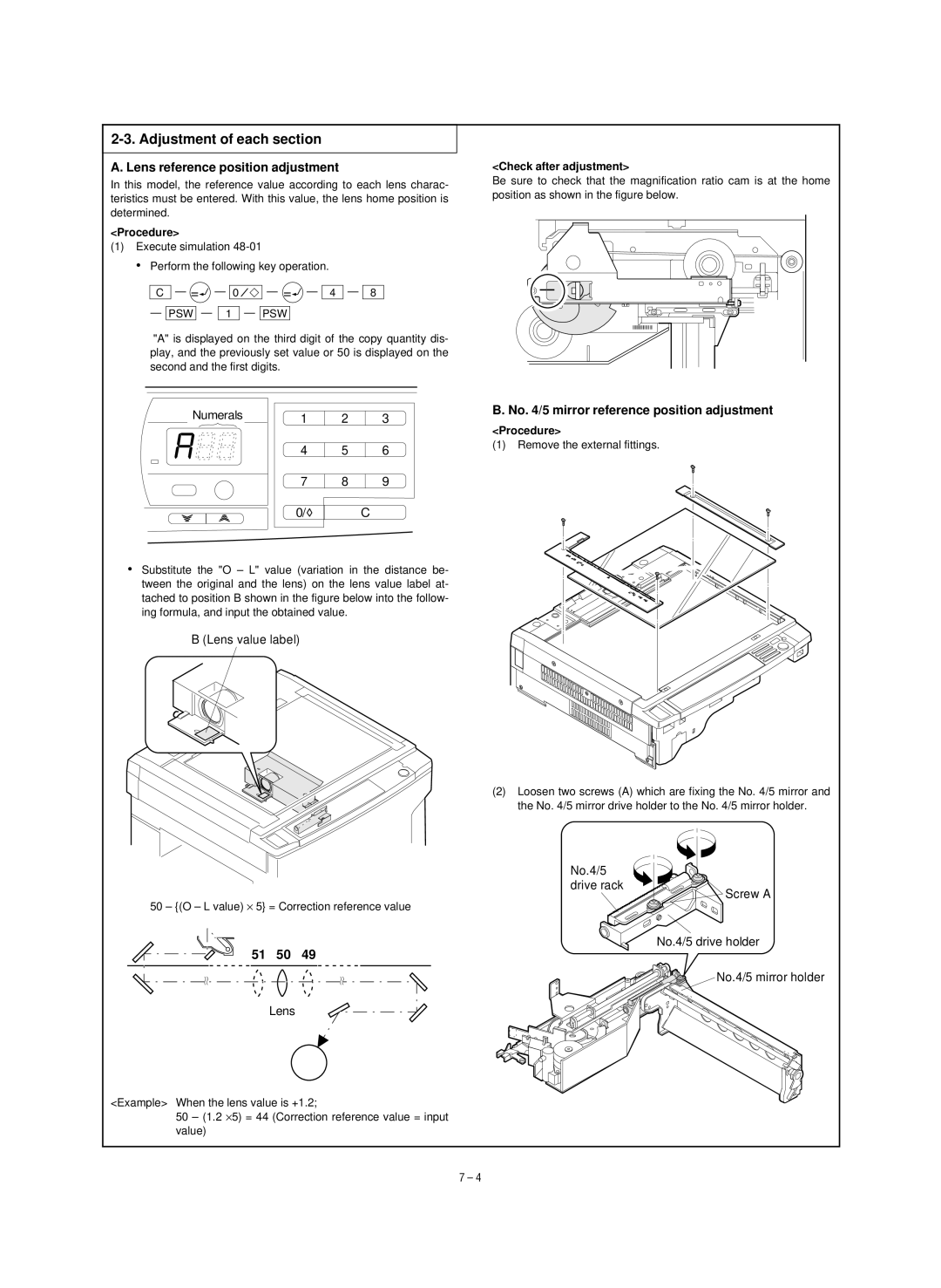
(2)Loosen two screws (A) which are fixing the No. 4/5 mirror and the No. 4/5 mirror drive holder to the No. 4/5 mirror holder.
No.4/5
drive rack
Screw A
No.4/5 drive holder
No.4/5 mirror holder
7 – 4