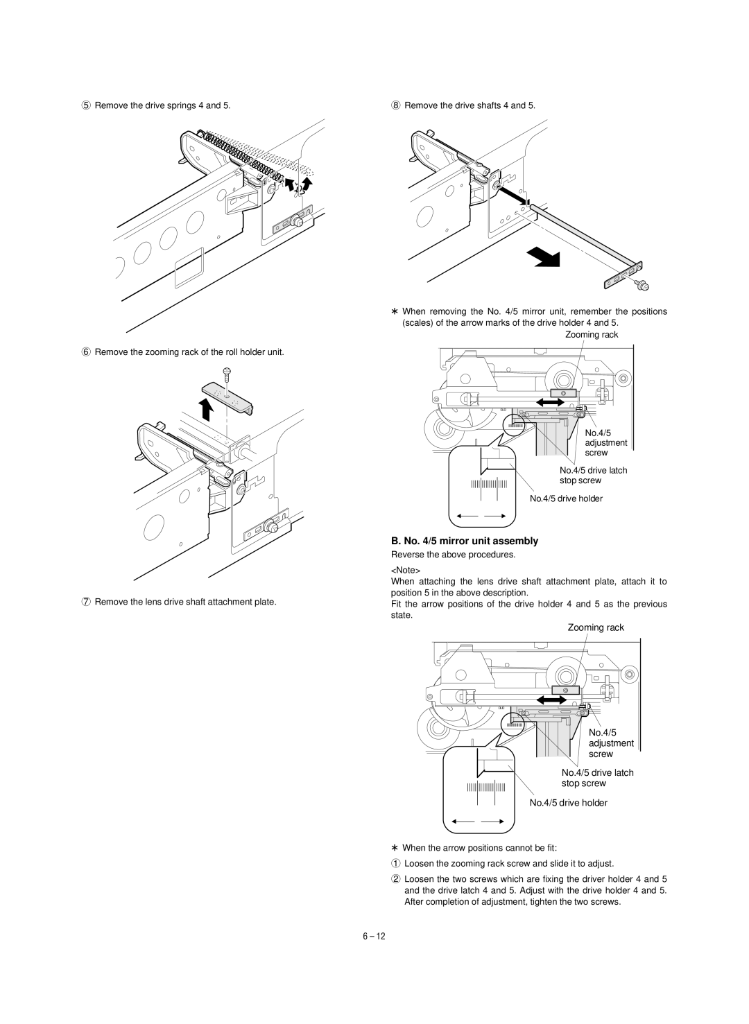
5Remove the drive springs 4 and 5.
6Remove the zooming rack of the roll holder unit.
7Remove the lens drive shaft attachment plate.
8Remove the drive shafts 4 and 5.
*When removing the No. 4/5 mirror unit, remember the positions (scales) of the arrow marks of the drive holder 4 and 5.
Zooming rack
No.4/5 adjustment screw
No.4/5 drive latch stop screw
No.4/5 drive holder
B. No. 4/5 mirror unit assembly
Reverse the above procedures.
<Note>
When attaching the lens drive shaft attachment plate, attach it to position 5 in the above description.
Fit the arrow positions of the drive holder 4 and 5 as the previous state.
Zooming rack
No.4/5 adjustment screw
No.4/5 drive latch stop screw
No.4/5 drive holder
*When the arrow positions cannot be fit:
1Loosen the zooming rack screw and slide it to adjust.
2Loosen the two screws which are fixing the driver holder 4 and 5 and the drive latch 4 and 5. Adjust with the drive holder 4 and 5. After completion of adjustment, tighten the two screws.
6 – 12