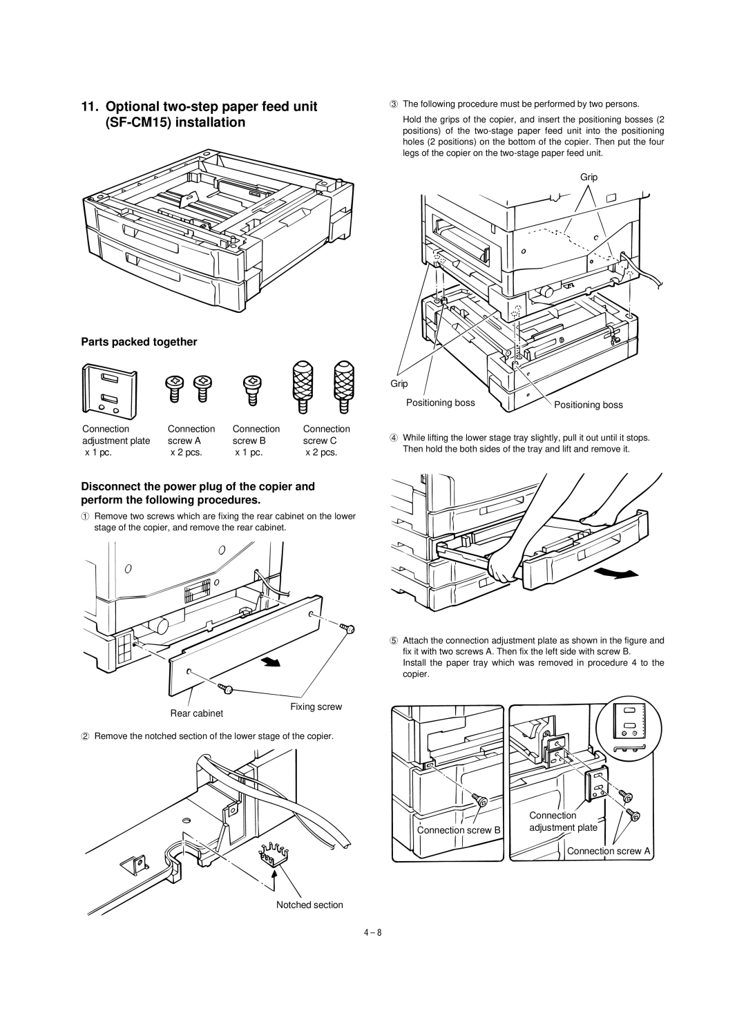
11.Optional two-step paper feed unit (SF-CM15) installation
Parts packed together
Connection | Connection | Connection | Connection |
adjustment plate | screw A | screw B | screw C |
x 1 pc. | x 2 pcs. | x 1 pc. | x 2 pcs. |
3The following procedure must be performed by two persons.
Hold the grips of the copier, and insert the positioning bosses (2 positions) of the
Grip
Grip
Positioning boss | Positioning boss |
4While lifting the lower stage tray slightly, pull it out until it stops. Then hold the both sides of the tray and lift and remove it.
Disconnect the power plug of the copier and perform the following procedures.
1Remove two screws which are fixing the rear cabinet on the lower stage of the copier, and remove the rear cabinet.
5Attach the connection adjustment plate as shown in the figure and fix it with two screws A. Then fix the left side with screw B.
Install the paper tray which was removed in procedure 4 to the copier.
Rear cabinet
Fixing screw
2Remove the notched section of the lower stage of the copier.
Connection
Connection screw B | adjustment plate |
|
Connection screw A
Notched section
4 – 8