Main code | Sub code |
|
|
|
|
|
| Content |
|
| |
|
|
|
|
|
|
|
|
|
|
|
|
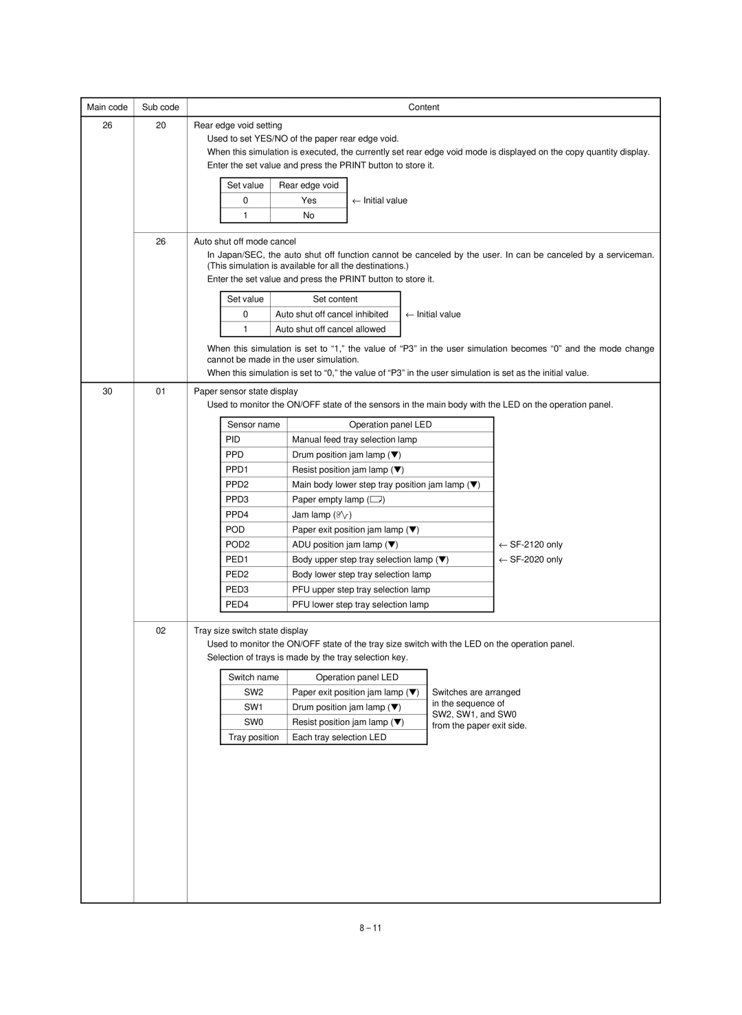
26 | 20 | Rear edge void setting |
|
|
|
|
|
|
| ||
|
| Used to set YES/NO of the paper rear edge void. |
|
|
|
| |||||
|
| When this simulation is executed, the currently set rear edge void mode is displayed on the copy quantity display. |
| ||||||||
|
| Enter the set value and press the PRINT button to store it. |
|
| |||||||
|
|
|
|
|
|
|
|
|
|
|
|
|
|
| Set value | Rear edge void |
|
|
|
|
|
| |
|
|
|
|
|
| ← Initial value |
|
| |||
|
|
| 0 |
| Yes |
|
| ||||
|
|
|
|
|
|
|
|
|
|
|
|
|
|
| 1 |
| No |
|
|
|
|
|
|
|
|
|
|
|
|
|
|
|
|
|
|
|
|
|
|
|
|
|
|
|
| ||
| 26 | Auto shut off mode cancel |
|
|
|
|
|
| |||
|
| In Japan/SEC, the auto shut off function cannot be canceled by the user. In can be canceled by a serviceman. |
| ||||||||
|
| (This simulation is available for all the destinations.) |
|
| |||||||
|
| Enter the set value and press the PRINT button to store it. |
|
| |||||||
|
|
|
|
|
|
|
|
|
|
| |
|
|
| Set value |
| Set content |
|
|
|
|
| |
|
|
|
|
|
|
| ← Initial value |
|
| ||
|
|
| 0 | Auto shut off cancel inhibited |
|
|
| ||||
|
|
|
|
|
|
|
|
|
|
| |
|
|
| 1 | Auto shut off cancel allowed |
|
|
|
|
| ||
|
|
|
|
|
|
|
|
|
| ||
|
| When this simulation is set to “1,” the value of “P3” in the user simulation becomes “0” and the mode | change | ||||||||
|
| cannot be made in the user simulation. |
|
|
|
| |||||
|
| When this simulation is set to “0,” the value of “P3” in the user simulation is set as the initial value. |
| ||||||||
|
|
|
|
|
|
|
|
|
| ||
30 | 01 | Paper sensor state display |
|
|
|
|
|
| |||
|
| Used to monitor the ON/OFF state of the sensors in the main body with the LED on the operation panel. |
| ||||||||
|
|
|
|
|
|
|
|
| |||
|
|
| Sensor name |
| Operation panel LED |
|
| ||||
|
|
|
|
|
|
|
|
| |||
|
|
| PID |
| Manual feed tray selection lamp |
|
| ||||
|
|
|
|
|
|
|
|
|
| ||
|
|
| PPD |
| Drum position jam lamp (▼) |
|
|
|
| ||
|
|
|
|
|
|
|
|
|
| ||
|
|
| PPD1 |
| Resist position jam lamp (▼) |
|
|
|
| ||
|
|
|
|
|
|
|
|
| |||
|
|
| PPD2 |
| Main body lower step tray position jam lamp (▼) |
|
| ||||
|
|
|
|
|
|
|
|
|
| ||
|
|
| PPD3 |
| Paper empty lamp (ç) |
|
|
|
| ||
|
|
|
|
|
|
|
|
|
| ||
|
|
| PPD4 |
| Jam lamp (ê) |
|
|
|
| ||
|
|
|
|
|
|
|
|
| |||
|
|
| POD |
| Paper exit position jam lamp (▼) |
|
| ||||
|
|
|
|
|
|
|
| ← |
| ||
|
|
| POD2 |
| ADU position jam lamp (▼) |
|
|
| |||
|
|
|
|
|
|
| ← |
| |||
|
|
| PED1 |
| Body upper step tray selection lamp (▼) |
| |||||
|
|
|
|
|
|
|
|
| |||
|
|
| PED2 |
| Body lower step tray selection lamp |
|
| ||||
|
|
|
|
|
|
|
|
| |||
|
|
| PED3 |
| PFU upper step tray selection lamp |
|
| ||||
|
|
|
|
|
|
|
|
| |||
|
|
| PED4 |
| PFU lower step tray selection lamp |
|
| ||||
|
|
|
|
|
|
|
|
|
|
| |
|
|
|
|
|
|
|
|
| |||
| 02 | Tray size switch state display |
|
|
|
|
|
| |||
|
| Used to monitor the ON/OFF state of the tray size switch with the LED on the operation panel. |
| ||||||||
|
| Selection of trays is made by the tray selection key. |
|
| |||||||
|
|
|
|
|
|
|
|
| |||
|
|
| Switch name | Operation panel LED |
|
|
|
| |||
|
|
|
|
|
|
|
| ||||
|
|
| SW2 |
| Paper exit position jam lamp (▼) | Switches are arranged |
| ||||
|
|
|
|
|
|
|
|
| in the sequence of |
| |
|
|
| SW1 |
| Drum position jam lamp (▼) |
|
| ||||
|
|
|
|
| SW2, SW1, and SW0 |
| |||||
|
|
|
|
|
|
|
|
|
| ||
|
|
| SW0 |
| Resist position jam lamp (▼) |
|
| ||||
|
|
|
|
| from the paper exit side. |
| |||||
|
|
|
|
|
|
|
|
|
| ||
|
|
| Tray position | Each tray selection LED |
|
|
|
| |||
|
|
|
|
|
|
|
|
|
|
|
|
|
|
|
|
|
|
|
|
|
|
|
|
8 – 11