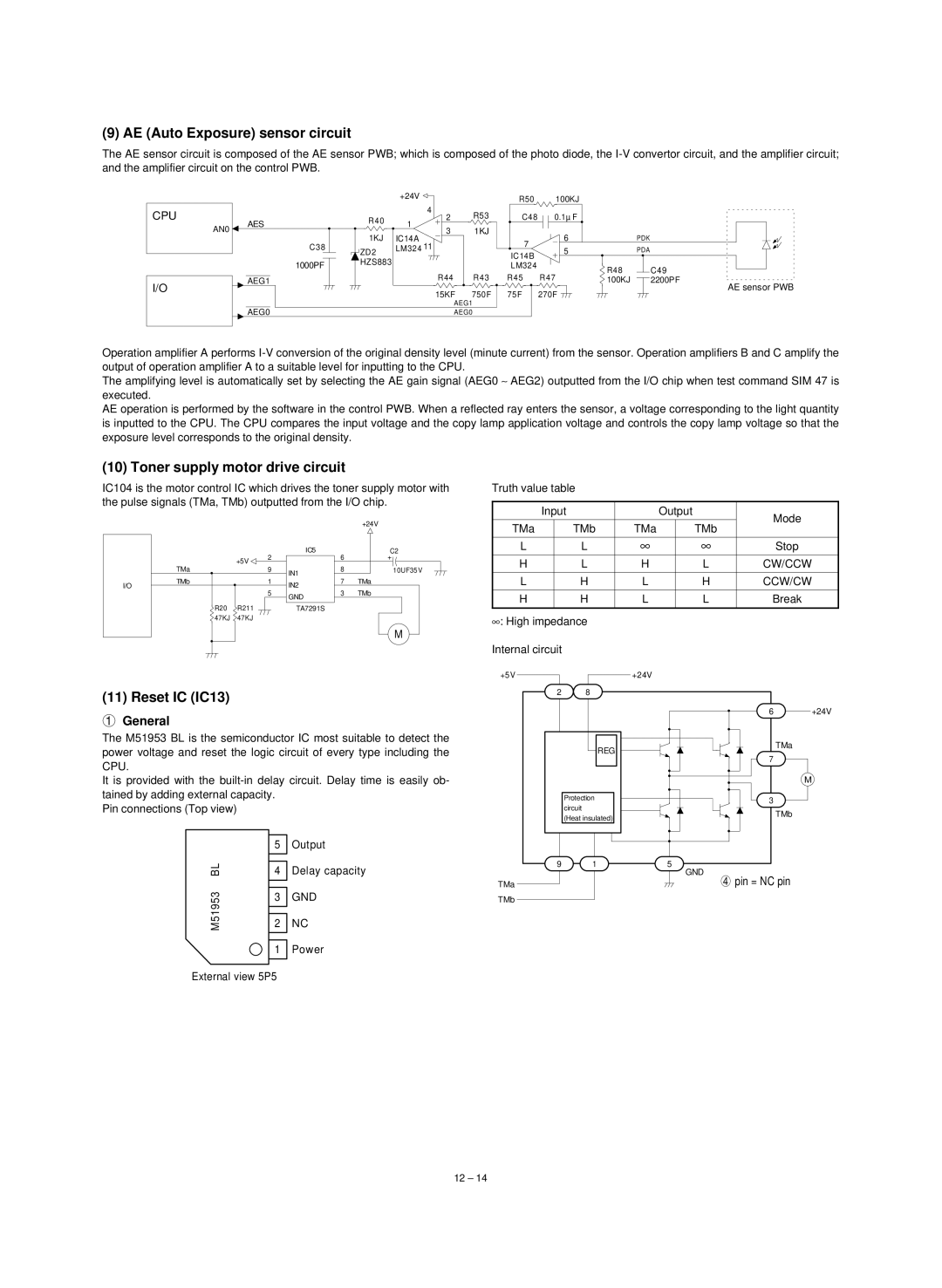
(9) AE (Auto Exposure) sensor circuit
The AE sensor circuit is composed of the AE sensor PWB; which is composed of the photo diode, the
|
|
|
|
| +24V |
CPU |
|
|
|
| 4 |
| AES |
| R40 | 1 | |
| AN0 |
| |||
|
|
| |||
|
|
| 1KJ | IC14A | |
|
|
|
| ||
|
|
| C38 | ZD2 | LM324 11 |
|
|
| 1000PF | HZS883 |
|
|
|
|
|
| |
I/O |
| AEG1 |
|
|
|
|
|
|
|
| |
|
| AEG0 |
|
|
|
|
| R50 | 100KJ |
2 | R53 | C48 | 0.1µ F |
3 | 1KJ |
| 6 |
|
| 7 | |
|
| 5 | |
|
| IC14B | |
|
|
| |
|
| LM324 |
|
R44 | R43 | R45 | R47 |
15KF 750F 75F 270F ![]()
AEG1
AEG0
| PDK | |
| PDA | |
R48 |
| C49 |
100KJ |
| 2200PF |
| ||
AE sensor PWB
Operation amplifier A performs
The amplifying level is automatically set by selecting the AE gain signal (AEG0 ∼ AEG2) outputted from the I/O chip when test command SIM 47 is executed.
AE operation is performed by the software in the control PWB. When a reflected ray enters the sensor, a voltage corresponding to the light quantity is inputted to the CPU. The CPU compares the input voltage and the copy lamp application voltage and controls the copy lamp voltage so that the exposure level corresponds to the original density.
(10) Toner supply motor drive circuit
IC104 is the motor control IC which drives the toner supply motor with the pulse signals (TMa, TMb) outputted from the I/O chip.
|
|
|
|
|
| +24V |
|
|
|
| IC5 |
| C2 |
|
| +5V | 2 |
| 6 | + |
|
|
|
|
|
| |
| TMa |
| 9 | IN1 | 8 | 10UF35V |
|
|
|
|
|
| |
I/O | TMb |
| 1 | IN2 | 7 | TMa |
|
| 5 | 3 | TMb | ||
|
|
| GND | |||
|
|
|
|
|
| |
| R20 | R211 |
| TA7291S |
|
|
| 47KJ | 47KJ |
|
|
|
|
M
Truth value table
| Input |
| Output | Mode | ||
|
|
|
|
|
| |
TMa |
| TMb | TMa |
| TMb |
|
|
|
|
|
|
|
|
L |
| L | ∞ |
| ∞ | Stop |
|
|
|
|
|
|
|
H |
| L | H |
| L | CW/CCW |
|
|
|
|
|
|
|
L |
| H | L |
| H | CCW/CW |
|
|
|
|
|
|
|
H |
| H | L |
| L | Break |
|
|
|
|
|
|
|
∞: High impedance Internal circuit
(11) Reset IC (IC13)
1General
The M51953 BL is the semiconductor IC most suitable to detect the power voltage and reset the logic circuit of every type including the CPU.
It is provided with the
Pin connections (Top view)
| 5 | Output |
BL | 4 | Delay capacity |
M51953 | 3 | GND |
| ||
| 2 | NC |
| 1 | Power |
+5V |
| +24V |
|
2 | 8 |
|
|
|
| 6 | +24V |
| REG | TMa |
|
| 7 |
| |
|
|
| |
|
|
| M |
| Protection | 3 |
|
| circuit | TMb |
|
| (Heat insulated) |
| |
|
|
| |
9 | 1 | 5 |
|
|
| GND |
|
TMa |
| 4 pin = NC pin |
|
TMb |
|
|
|
External view 5P5
12 – 14