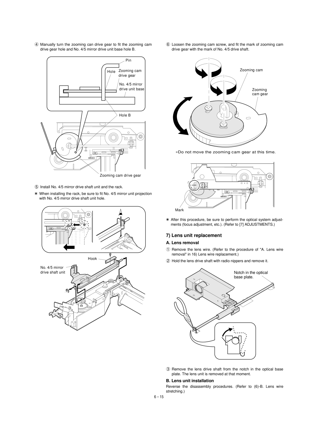
4Manually turn the zooming can drive gear to fit the zooming cam drive gear hole and No. 4/5 mirror drive unit base hole B.
Pin
Hole Zooming cam drive gear
No. 4/5 mirror |
drive unit base |
Hole B
6Loosen the zooming cam screw, and fit the mark of zooming cam drive gear with the mark of No. 4/5 drive shaft.
Zooming cam
Zooming cam gear
Zooming cam drive gear
5Install No. 4/5 mirror drive shaft unit and the rack.
*When installing the rack, be sure to fit No. 4/5 mirror unit projection with No. 4/5 mirror drive shaft unit hole.
Hook ![]()
No. 4/5 mirror ![]()
![]() drive shaft unit
drive shaft unit
∗Do not move the zooming cam gear at this time.
Mark
*After this procedure, be sure to perform the optical system adjust- ments (focus adjustment, etc.). (Refer to [7] ADJUSTMENTS.)
7) Lens unit replacement
A. Lens removal
1Remove the lens wire. (Refer to the procedure of "A. Lens wire removal" in 16) Lens wire replacement.)
2Hold the lens drive shaft with radio nippers and remove it.
Notch in the optical base plate. ![]()
3Remove the lens drive shaft from the notch in the optical base plate. The lens unit is removed at that moment.
B. Lens unit installation
Reverse the disassembly procedures. (Refer to
6 – 15