(4)Measure the distance between the copy paper lead edge and the copy image lead edge in each copy. Obtain
If the
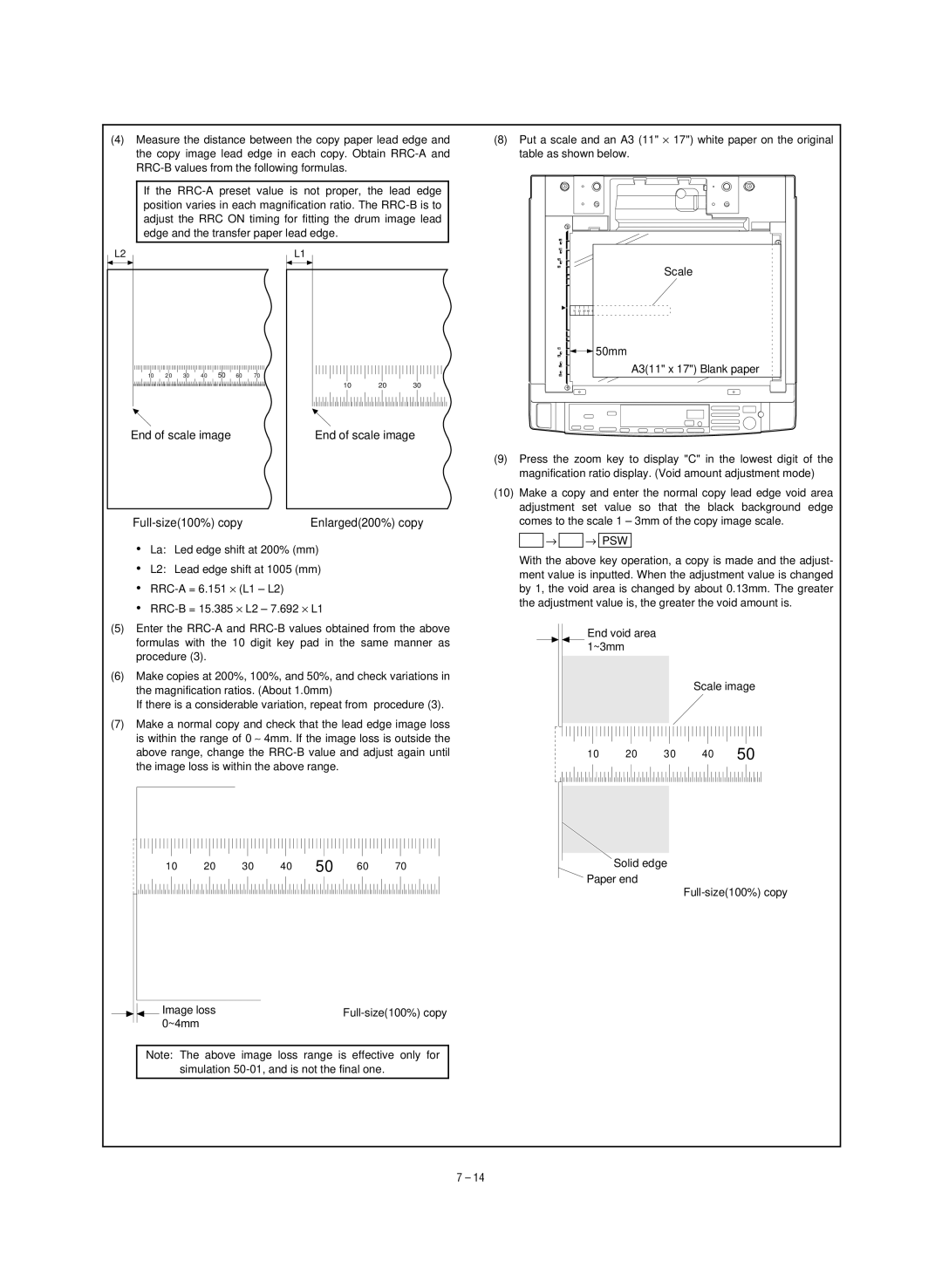
(8)Put a scale and an A3 (11" × 17") white paper on the original table as shown below.
L2
10 20 30 40 50 60 70
End of scale image
L1
10 20 30
End of scale image
|
|
|
|
|
|
|
|
| Scale |
10 | 20 | 30 40 | 50 | 60 | 70 | 80 | 90 | 50 | 100 110 12 0130 140 |
|
|
|
| 50mm | |||||
|
|
|
|
|
|
|
|
| A3(11" x 17") Blank paper |
|
|
|
|
|
|
|
|
|
|
Enlarged(200%) copy |
•La: Led edge shift at 200% (mm)
•L2: Lead edge shift at 1005 (mm)
•
•
(5)Enter the
(6)Make copies at 200%, 100%, and 50%, and check variations in the magnification ratios. (About 1.0mm)
If there is a considerable variation, repeat from procedure (3).
(7)Make a normal copy and check that the lead edge image loss is within the range of 0 ∼ 4mm. If the image loss is outside the above range, change the
10 | 20 | 30 | 40 | 50 | 60 | 70 |
Image loss | |
0~4mm |
|
Note: The above image loss range is effective only for simulation
(9)Press the zoom key to display "C" in the lowest digit of the magnification ratio display. (Void amount adjustment mode)
(10)Make a copy and enter the normal copy lead edge void area adjustment set value so that the black background edge comes to the scale 1 – 3mm of the copy image scale.
![]()
![]() →
→ ![]()
![]() → PSW
→ PSW
With the above key operation, a copy is made and the adjust- ment value is inputted. When the adjustment value is changed by 1, the void area is changed by about 0.13mm. The greater the adjustment value is, the greater the void amount is.
End void area 1~3mm
Scale image
10 20 30 40 50
Solid edge
Paper end
7 – 14