B. Original detecting level adjustment
(Original detecting judgement level input)
This adjustment is to set the reference value for judgement of presence or absence of an original and to monitor the sensor status.
1C → ë → 0 → ë → 4 → 1 →
PSW → 2 → PSW
At that time, the ready lamp lights up and "1" is displayed on the copy quantity display.
2With the original cover open without original, press the PRINT button. (The sensor level without original is read.) The copy quantity display is shifted from 1 to 2.
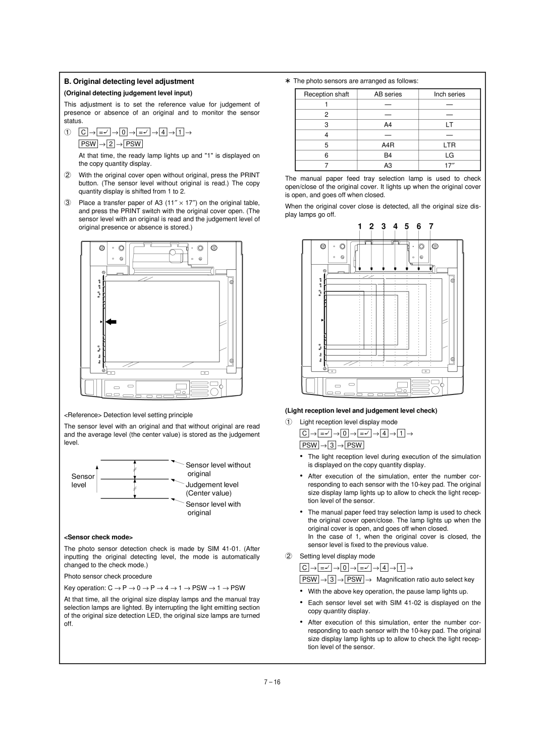
3Place a transfer paper of A3 (11″ × 17″) on the original table, and press the PRINT switch with the original cover open. (The sensor level with an original is read and the judgement level of original presence or absence is stored.)
<Reference> Detection level setting principle
The sensor level with an original and that without original are read and the average level (the center value) is stored as the judgement level.
*The photo sensors are arranged as follows:
Reception shaft | AB series | Inch series |
|
|
|
1 | — | — |
|
|
|
2 | — | — |
|
|
|
3 | A4 | LT |
|
|
|
4 | — | — |
|
|
|
5 | A4R | LTR |
|
|
|
6 | B4 | LG |
|
|
|
7 | A3 | 17″ |
|
|
|
The manual paper feed tray selection lamp is used to check open/close of the original cover. It lights up when the original cover is open, and goes off when closed.
When the original cover close is detected, all the original size dis- play lamps go off.
1 2 3 4 5 6 7
(Light reception level and judgement level check)
1Light reception level display mode
C → ë → 0 → ë → 4 → 1 →
PSW → 3 → PSW
Sensor level
<Sensor check mode>
Sensor level without original
Judgement level (Center value)
Sensor level with original
• The light reception level during execution of the simulation |
is displayed on the copy quantity display. |
• After execution of the simulation, enter the number cor- |
responding to each sensor with the |
size display lamp lights up to allow to check the light recep- |
tion level of the sensor. |
• The manual paper feed tray selection lamp is used to check |
the original cover open/close. The lamp lights up when the |
original cover is open, and goes off when closed. |
In the case of 1, when the original cover is closed, the |
sensor level is fixed to the previous value. |
The photo sensor detection check is made by SIM
Photo sensor check procedure
Key operation: C → P → 0 → P → 4 → 1 → PSW → 1 → PSW
At that time, all the original size display lamps and the manual tray selection lamps are lighted. By interrupting the light emitting section of the original size detection LED, the original size lamps are turned off.
2Setting level display mode
C → ë → 0 → ë → 4 → 1 →
PSW → 3 → PSW → Magnification ratio auto select key
•With the above key operation, the pause lamp lights up.
•Each sensor level set with SIM
•After execution of this simulation, enter the number cor- responding to each sensor with the
7 – 16
