5. Details of simulations
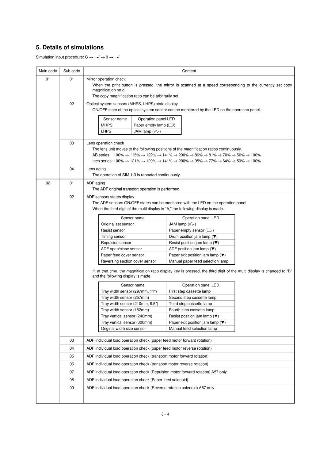
Simulation input procedure: C → ë → 0 → ë
Main code | Sub code |
|
|
| Content |
|
|
|
|
|
|
01 | 01 | Mirror operation check |
|
| |
|
| When the print button is pressed, the mirror is scanned at a speed corresponding to the currently set copy | |||
|
| magnification ratio. |
|
| |
|
| The copy magnification ratio can be arbitrarily set. | |||
|
|
|
|
|
|
| 02 | Optical system sensors (MHPS, LHPS) state display | |||
|
| ON/OFF state of the optical system sensor can be monitored by the LED on the operation panel. | |||
|
|
|
|
|
|
|
|
| Sensor name | Operation panel LED |
|
|
|
|
|
|
|
|
|
| MHPS | Paper empty lamp (ç) |
|
|
|
|
|
|
|
|
|
| LHPS | JAM lamp (ê) |
|
|
|
|
|
|
|
|
|
|
|
| |
| 03 | Lens operation check |
|
| |
|
| The lens unit moves to the following positions of the magnification ratios continuously. | |||
|
| AB series: 100% → 115% → 122% → 141% → 200% → 86% → 81% → 70% → 50% → 100% | |||
|
| Inch series: 100% → 121% → 129% → 141% → 200% → 95% → 77% → 64% → 50% → 100% | |||
|
|
|
|
| |
| 04 | Lens aging |
|
| |
|
| The operation of SIM | |||
|
|
|
|
| |
02 | 01 | ADF aging |
|
| |
The ADF original transport operation is performed.
02 | ADF sensors states display |
The ADF sensors ON/OFF states can be monitored with the LED on the operation panel.
When the third digit of the multi display is “A,” the following display is made.
Sensor name | Operation panel LED |
|
|
Original set sensor | JAM lamp (ê) |
|
|
Resist sensor | Paper empty sensor (ç) |
|
|
Timing sensor | Drum position jam lamp (▼) |
|
|
Repulsion sensor | Resist position jam lamp (▼) |
|
|
ADF open/close sensor | ADF position jam lamp (▼) |
|
|
Paper feed cover sensor | Paper exit position jam lamp (▼) |
|
|
Reversing section cover sensor | Manual paper feed selection lamp |
|
|
If, at that time, the magnification ratio display key is pressed, the third digit of the multi display is changed to “B” and the following display is made.
|
| Sensor name | Operation panel LED |
|
|
|
|
|
|
|
| Tray width sensor (297mm, 11") | First step cassette lamp |
|
|
|
|
|
|
|
| Tray width sensor (257mm) | Second step cassette lamp |
|
|
|
|
|
|
|
| Tray width sensor (210mm, 8.5") | Third step cassette lamp |
|
|
|
|
|
|
|
| Tray width sensor (182mm) | Fourth step cassette lamp |
|
|
|
|
|
|
|
| Tray vertical sensor (240mm) | Resist position jam lamp (▼) |
|
|
|
|
|
|
|
| Tray vertical sensor (300mm) | Paper exit position jam lamp (▼) |
|
|
|
|
|
|
|
| Original width size sensor | Manual feed selection lamp |
|
|
|
|
|
|
|
|
| ||
03 | ADF individual load operation check (paper feed motor forward rotation) |
| ||
|
|
| ||
04 | ADF individual load operation check (paper feed motor reverse rotation) |
| ||
|
|
| ||
05 | ADF individual load operation check (transport motor forward rotation) |
| ||
|
|
| ||
06 | ADF individual load operation check (transport motor reverse rotation) |
| ||
|
|
| ||
07 | ADF individual load operation check (Repulsion motor forward rotation) A57 only |
| ||
|
|
| ||
08 | ADF individual load operation check (Paper feed solenoid) |
| ||
|
|
| ||
09 | ADF individual load operation check (Reverse rotation solenoid) A57 only |
| ||
8 – 4