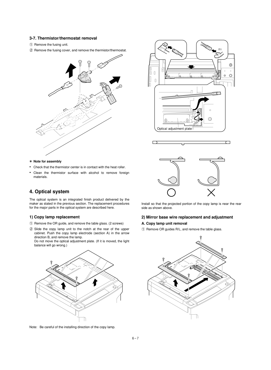
3-7. Thermistor/thermostat removal
1 Remove the fusing unit.
2 Remove the fusing cover, and remove the thermistor/thermostat. | (B) |
Optical adjustment plate
*Note for assembly
•Check that the thermistor center is in contact with the heat roller.
•Clean the thermistor surface with alcohol to remove foreign
materials.
4. Optical system
The optical system is an integrated finish product delivered by the maker as stated in the previous section. The replacement procedures for the major parts in the optical system are described here.
1) Copy lamp replacement
1Remove the OR guide, and remove the table glass. (2 screws)
2Slide the copy lamp unit to the notch at the rear of the upper cabinet. Push the copy lamp electrode (section A) in the arrow direction B, and remove the lamp.
Do not move the optical adjustment plate. (If it is moved, the light balance will go wrong.)
Note: Be careful of the installing direction of the copy lamp.
Install so that the projected portion of the copy lamp is near the rear
side as shown above.
2) Mirror base wire replacement and adjustment
A. Copy lamp unit removal
1Remove OR guides R/L, and remove the table glass.
6 – 7
