Connect the rear side of the copier with two connection screws C.
Connection screw C
Connection screw C
6Remove the connecter which is fixed to the rear cabinet of the
4P connector
16P connector
4P connector
Fixing tape
7Install the rear cabinet which was removed in procedure 1 to the original postilion, and fix it with two screws.
Rear cabinet
Fixing screw
8Adjust according to "9. Center shift adjustment" in [4] UNPACK-
ING AND INSTALLATION.
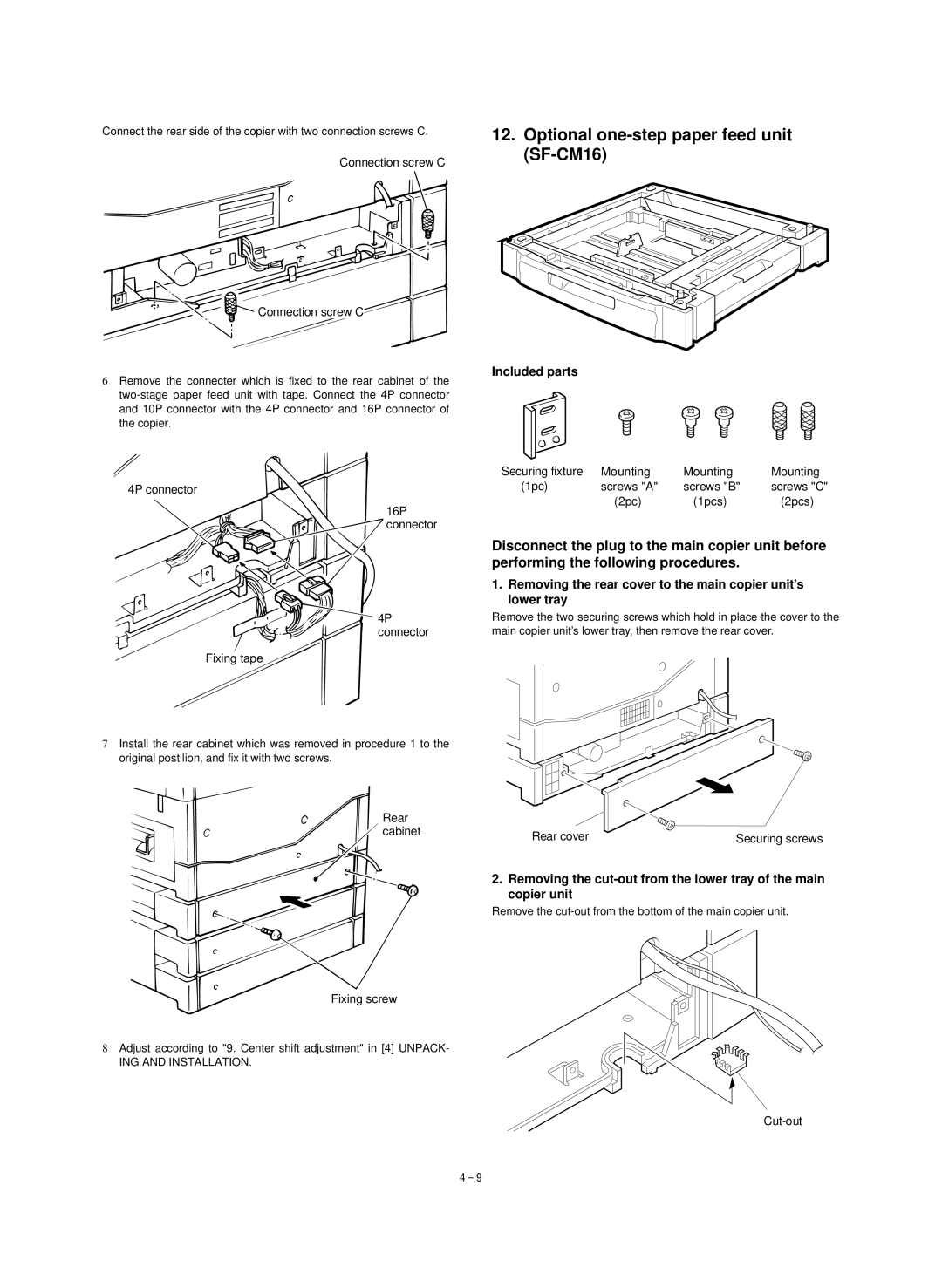
12.Optional one-step paper feed unit (SF-CM16)
Included parts
Securing fixture | Mounting | Mounting | Mounting |
(1pc) | screws "A" | screws "B" | screws "C" |
| (2pc) | (1pcs) | (2pcs) |
Disconnect the plug to the main copier unit before performing the following procedures.
1.Removing the rear cover to the main copier unit's lower tray
Remove the two securing screws which hold in place the cover to the main copier unit's lower tray, then remove the rear cover.
Rear cover | Securing screws |
2.Removing the
Remove the
4 – 9