(6) Heater lamp control circuit
|
|
|
| +5V1 |
|
|
R67 | R71 |
|
|
|
|
|
1KJ | 47KJ |
|
|
|
|
|
11 |
|
|
|
|
|
|
13 | R7 5 |
|
|
|
|
|
10 | Q7 |
|
| C6 |
| |
|
|
|
| |||
IC20D | 75J | 2SC945 |
|
| R80 | |
NJM2901 | C7 |
|
|
|
| |
R6 8 |
|
| R84 |
| 24KJ | CPU 17PIN |
|
|
|
|
| ||
5.6KJ |
|
| D41 | 0.22µ F |
| |
0.22µ F |
| 10KJ |
| |||
|
|
|
|
|
|
|
|
|
|
|
|
|
|
|
|
|
|
|
| Vref |
|
|
|
|
|
|
|
|
|
|
| R91 |
| R87 | R89 |
|
|
|
|
|
|
|
|
|
|
|
|
| 8.2KJ |
| 1MJ | 4.7KF |
|
|
|
|
|
|
|
|
|
|
|
| 8 |
|
|
|
|
|
|
|
|
|
|
|
|
|
|
|
| 14 |
|
| D3 8 |
|
|
|
|
|
|
|
|
|
|
|
|
| 9 |
|
|
|
|
|
|
|
|
|
|
|
|
|
| D6 | D7 | IC20C |
| C55 | MA700 |
|
|
|
|
|
|
| D16 |
|
|
| NJM2901 |
|
|
|
|
| ||||
|
|
|
|
|
|
|
|
|
|
|
|
|
| |||
|
|
|
|
|
|
|
|
| R93 |
|
|
| R9 2 |
|
|
|
|
|
| DSM101 |
|
|
|
|
| 680J |
|
|
|
|
|
| |
|
|
|
|
|
|
|
|
| 22000PF | 47KF |
|
|
| |||
8 ~ 20 | PR | Q 5 |
|
|
|
|
|
|
|
|
|
| ||||
|
|
|
|
|
|
|
|
|
|
|
|
|
| |||
| 2SA573 |
|
|
|
|
|
|
|
|
|
|
|
|
|
| |
|
|
|
|
|
|
|
|
|
|
|
|
|
|
|
| |
|
| R54 | R53 | +24V |
|
|
|
|
|
|
|
|
|
|
|
|
|
|
|
| IC9 |
|
|
|
|
|
|
|
|
|
|
| |
|
| 5.6KJ | 47KJ |
|
|
|
|
|
|
|
|
|
|
|
| |
|
| 16 |
|
| 1 |
|
|
|
|
|
|
|
|
| ||
|
|
|
| O1 | I1 |
|
|
|
|
|
|
|
|
| ||
|
|
|
| 15 | 2 |
|
|
|
|
|
|
|
|
| ||
|
|
|
| 14 | O2 | I2 | 3 |
|
|
|
|
|
|
| Heat roller | |
|
|
|
| O3 | I3 |
| R32 | PR |
|
|
|
| ||||
|
|
|
| 13 | O4 | I4 | 4 |
| 2.7KJ |
| CPU |
|
|
|
| |
|
|
|
| 12 | O5 | I5 | 5 |
| HL |
| AN1 |
|
|
|
| |
|
|
|
| 11 | O6 | I6 | 6 |
|
|
|
|
|
|
| ||
|
|
|
| 10 | O7 | I7 | 7 |
|
|
|
|
|
|
|
|
|
|
|
|
| 9 | 8 |
|
|
|
|
|
|
|
|
| ||
|
|
|
|
| SK | G |
|
|
|
|
|
|
|
|
|
|
|
|
|
|
| ULN2004 |
|
|
|
|
|
|
|
|
|
| |
|
|
|
|
| R35 |
|
|
|
|
|
|
|
| PR |
|
|
|
|
|
|
|
|
|
| +5V2 |
|
| L2 |
|
|
|
| |
|
|
|
|
|
|
|
|
|
|
|
|
|
|
| ||
|
|
|
|
| 270J |
|
|
|
|
|
|
|
|
|
| |
|
|
|
|
|
|
|
|
|
|
|
|
|
|
|
| |
|
|
|
|
| 1/4W |
|
|
| 10K |
|
|
|
|
|
|
|
|
|
|
|
|
| Q3 |
| 2.2K |
|
|
|
|
| GATE |
| |
|
|
|
|
|
|
|
|
|
|
|
|
| T1 | |||
|
|
|
|
| DTA123Y5 |
|
|
|
|
|
|
|
| |||
|
|
|
|
|
|
|
|
|
|
|
|
|
| |||
|
|
|
|
|
|
|
|
|
|
|
|
|
|
|
| T2 |
|
|
|
|
|
|
|
|
|
|
|
|
| PR | GND |
|
|
|
|
|
|
|
|
|
|
|
|
|
|
| AC PWB | AC PWB |
| |
|
|
|
|
|
|
|
|
|
|
|
|
|
|
| 200V AREA |
|
MLSW
ML
AC
MLSW | ML |
|
ML : 1KW
N1
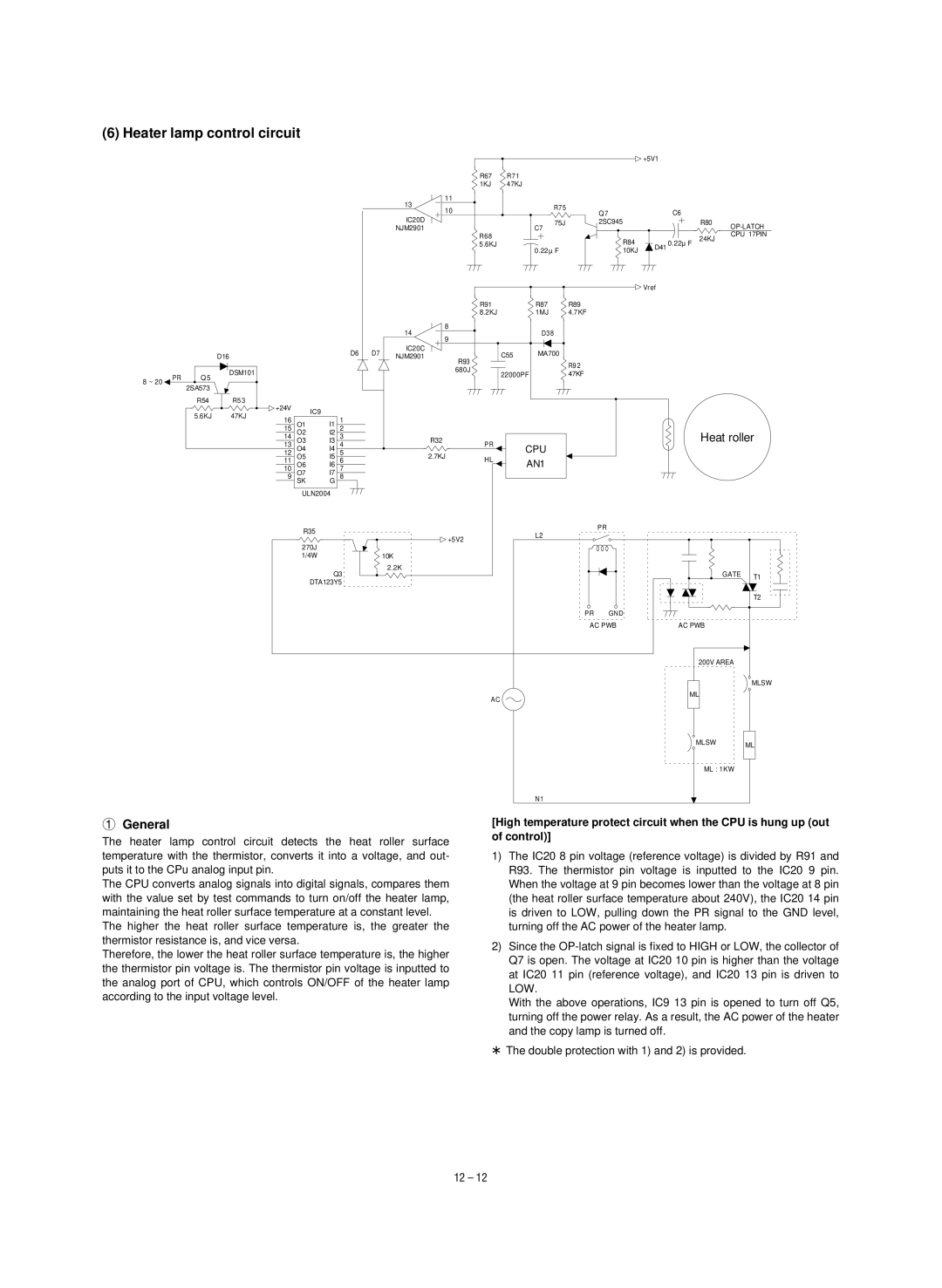
1General
The heater lamp control circuit detects the heat roller surface temperature with the thermistor, converts it into a voltage, and out- puts it to the CPu analog input pin.
The CPU converts analog signals into digital signals, compares them with the value set by test commands to turn on/off the heater lamp, maintaining the heat roller surface temperature at a constant level.
The higher the heat roller surface temperature is, the greater the thermistor resistance is, and vice versa.
Therefore, the lower the heat roller surface temperature is, the higher the thermistor pin voltage is. The thermistor pin voltage is inputted to the analog port of CPU, which controls ON/OFF of the heater lamp according to the input voltage level.
[High temperature protect circuit when the CPU is hung up (out of control)]
1)The IC20 8 pin voltage (reference voltage) is divided by R91 and R93. The thermistor pin voltage is inputted to the IC20 9 pin. When the voltage at 9 pin becomes lower than the voltage at 8 pin (the heat roller surface temperature about 240V), the IC20 14 pin is driven to LOW, pulling down the PR signal to the GND level, turning off the AC power of the heater lamp.
2)Since the
With the above operations, IC9 13 pin is opened to turn off Q5, turning off the power relay. As a result, the AC power of the heater and the copy lamp is turned off.
*The double protection with 1) and 2) is provided.
12 – 12