G. Vertical skew adjustment
a.This adjustment is performed when a skew copy is made as shown below or when a part of the mirror base drive wire or the No. 1/2 mirror base is replaced.
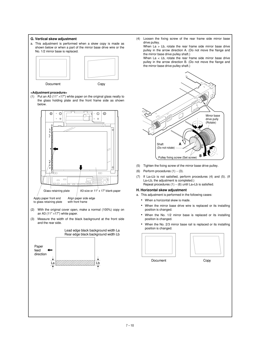
(4)Loosen the fixing screw of the rear frame side mirror base drive pulley.
When La > Lb, rotate the rear frame side mirror base drive pulley in the arrow direction A. (Do not move the flange and the mirror base drive pulley shaft.)
When La < Lb, rotate the rear frame side mirror base drive pulley in the arrow direction B. (Do not move the flange and the mirror base drive pulley shaft.)
DocumentCopy
<Adjustment procedure>
(1)Put an A3 (11" ×17") white paper on the original glass neatly to the glass holding plate and the front frame side as shown below.
Glass retaining plate | ||
Apply paper front end | Align paper side edge | |
to glass retaining plate | with front frame | |
(2)With the original cover open, make a normal (100%) copy on an A3 (11" ×17") white paper.
(3)Measure the width of the black background at the front side and the rear side.
Lead edge black background width La
Rear edge black background width Lb
Paper feed ![]() direction
direction
La ![]() Lb
Lb
Mirror base drive pully (Rotate)
Shaft | A |
(Do not rotate) |
|
Pulley fixing screw (Set screw) B
(5)Tighten the fixing screw of the mirror base drive pulley.
(6)Perform procedures (1) ∼ (3).
(7)If La=Lb is not satisfied, perform procedures (4) and (5). (If
La=Lb, the adjustment is completed.)
Repeat procedures (1) ∼ (6) until La=Lb is satisfied.
H. Horizontal skew adjustment
a.This adjustment is performed in the following cases:
•When a horizontal skew is made.
•When the mirror base drive wire is replaced or its installing position is changed.
•When the No. 1/2 mirror base is replaced or its installing position is changed.
•When the No. 2/3 mirror base rail is replaced or its installing position is changed.
Document | Copy |
7 – 10