Main code | Sub code |
|
|
| Content | |
|
|
|
|
|
|
|
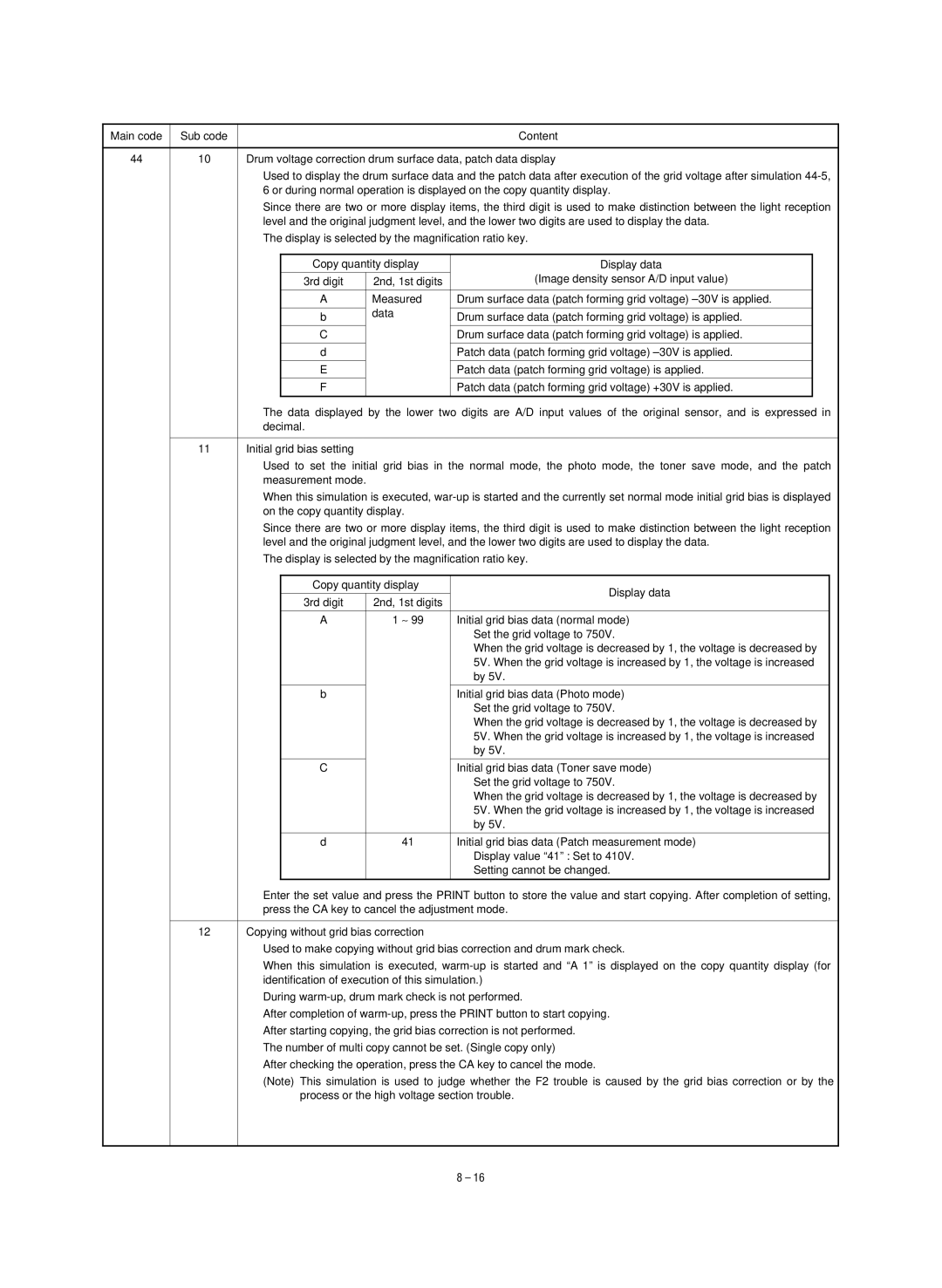
44 | 10 | Drum voltage correction drum surface data, patch data display | ||||
|
| Used to display the drum surface data and the patch data after execution of the grid voltage after simulation | ||||
|
| 6 or during normal operation is displayed on the copy quantity display. | ||||
|
| Since there are two or more display items, the third digit is used to make distinction between the light reception | ||||
|
| level and the original judgment level, and the lower two digits are used to display the data. | ||||
|
| The display is selected by the magnification ratio key. | ||||
|
|
|
|
|
|
|
|
|
| Copy quantity display | Display data |
| |
|
|
|
|
| (Image density sensor A/D input value) |
|
|
|
| 3rd digit | 2nd, 1st digits | ||
|
|
|
|
|
|
|
|
|
| A | Measured | Drum surface data (patch forming grid voltage) |
|
|
|
|
| data |
|
|
|
|
| b | Drum surface data (patch forming grid voltage) is applied. |
| |
|
|
|
|
| ||
|
|
|
|
|
|
|
|
|
| C |
| Drum surface data (patch forming grid voltage) is applied. |
|
|
|
|
|
|
|
|
|
|
| d |
| Patch data (patch forming grid voltage) |
|
|
|
|
|
|
|
|
|
|
| E |
| Patch data (patch forming grid voltage) is applied. |
|
|
|
|
|
|
|
|
|
|
| F |
| Patch data (patch forming grid voltage) +30V is applied. |
|
|
|
|
|
|
|
|
The data displayed by the lower two digits are A/D input values of the original sensor, and is expressed in decimal.
11 | Initial grid bias setting |
Used to set the initial grid bias in the normal mode, the photo mode, the toner save mode, and the patch measurement mode.
When this simulation is executed,
Since there are two or more display items, the third digit is used to make distinction between the light reception level and the original judgment level, and the lower two digits are used to display the data.
The display is selected by the magnification ratio key.
Copy quantity display | Display data | |
|
| |
3rd digit | 2nd, 1st digits |
|
|
|
|
A | 1 ∼ 99 | Initial grid bias data (normal mode) |
|
| Set the grid voltage to 750V. |
|
| When the grid voltage is decreased by 1, the voltage is decreased by |
|
| 5V. When the grid voltage is increased by 1, the voltage is increased |
|
| by 5V. |
|
|
|
b |
| Initial grid bias data (Photo mode) |
|
| Set the grid voltage to 750V. |
|
| When the grid voltage is decreased by 1, the voltage is decreased by |
|
| 5V. When the grid voltage is increased by 1, the voltage is increased |
|
| by 5V. |
|
|
|
C |
| Initial grid bias data (Toner save mode) |
|
| Set the grid voltage to 750V. |
|
| When the grid voltage is decreased by 1, the voltage is decreased by |
|
| 5V. When the grid voltage is increased by 1, the voltage is increased |
|
| by 5V. |
|
|
|
d | 41 | Initial grid bias data (Patch measurement mode) |
|
| Display value “41” : Set to 410V. |
|
| Setting cannot be changed. |
|
|
|
Enter the set value and press the PRINT button to store the value and start copying. After completion of setting, press the CA key to cancel the adjustment mode.
12 | Copying without grid bias correction |
Used to make copying without grid bias correction and drum mark check.
When this simulation is executed,
During
After completion of
After starting copying, the grid bias correction is not performed.
The number of multi copy cannot be set. (Single copy only)
After checking the operation, press the CA key to cancel the mode.
(Note) This simulation is used to judge whether the F2 trouble is caused by the grid bias correction or by the process or the high voltage section trouble.
8 – 16