(20) Original size sensing
The original size is sensed by the original interruption system.
The LED in the rear frame side emits light to the table glass surface. The original interrupts this light, and its size is detected.
Mirror base scan speed
Lens and mirror positions |
Table glass
Light receiving
Light emit
Copy paper | are changed to adjust the |
magnification ratio |
feed derection
Mirror scan speed is cahnged to adjust the magnification ratio Mirror scan speed Drum rotation speed<Mirror scan speed
Enlargement
2. Basic operations
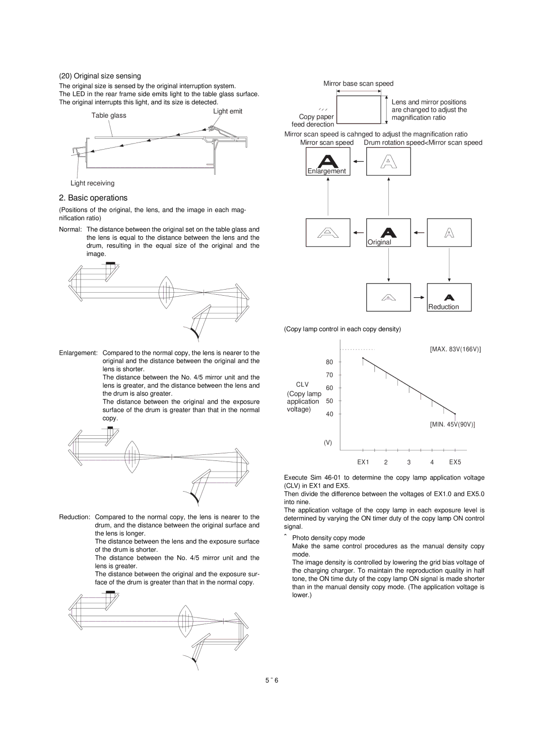
(Positions of the original, the lens, and the image in each mag- nification ratio)
Normal: The distance between the original set on the table glass and the lens is equal to the distance between the lens and the drum, resulting in the equal size of the original and the image.
Enlargement: Compared to the normal copy, the lens is nearer to the original and the distance between the original and the lens is shorter.
The distance between the No. 4/5 mirror unit and the lens is greater, and the distance between the lens and the drum is also greater.
The distance between the original and the exposure surface of the drum is greater than that in the normal copy.
Reduction: Compared to the normal copy, the lens is nearer to the drum, and the distance between the original surface and the lens is longer.
The distance between the lens and the exposure surface of the drum is shorter.
The distance between the No. 4/5 mirror unit and the lens is greater.
The distance between the original and the exposure sur- face of the drum is greater than that in the normal copy.
Original
Reduction
(Copy lamp control in each copy density)
|
|
|
| [MAX. 83V(166V)] | |
| 80 |
|
|
|
|
| 70 |
|
|
|
|
CLV | 60 |
|
|
|
|
(Copy lamp |
|
|
|
| |
50 |
|
|
|
| |
application |
|
|
|
| |
voltage) | 40 |
|
|
|
|
|
|
|
|
| |
|
|
|
| [MIN. 45V(90V)] | |
| (V) |
|
|
|
|
| EX1 | 2 | 3 | 4 | EX5 |
Execute Sim
Then divide the difference between the voltages of EX1.0 and EX5.0 into nine.
The application voltage of the copy lamp in each exposure level is determined by varying the ON timer duty of the copy lamp ON control signal.
•Photo density copy mode
Make the same control procedures as the manual density copy mode.
The image density is controlled by lowering the grid bias voltage of the charging charger. To maintain the reproduction quality in half tone, the ON time duty of the copy lamp ON signal is made shorter than in the manual density copy mode. (The application voltage is lower.)
5 – 6