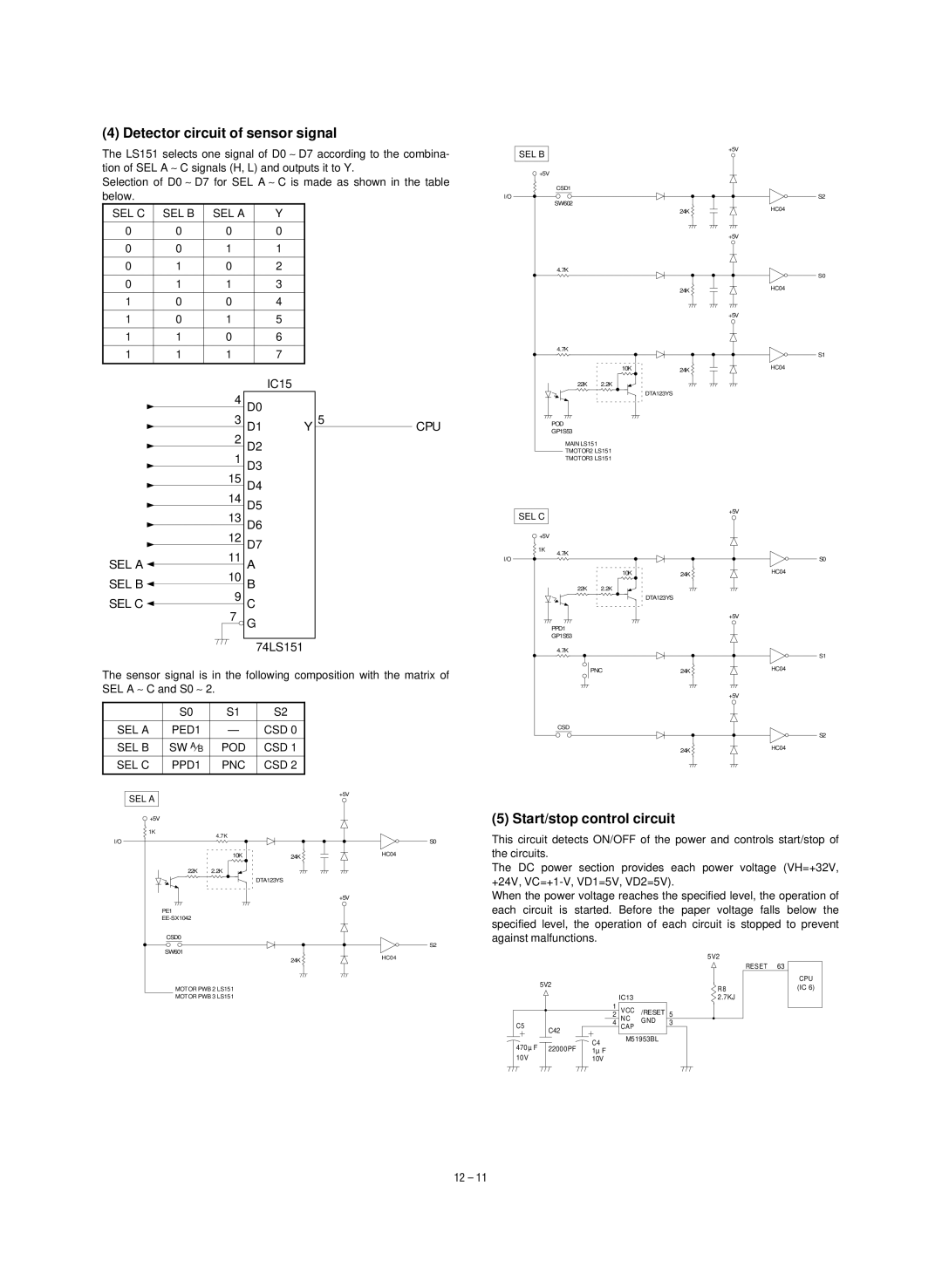
(4) Detector circuit of sensor signal
The LS151 selects one signal of D0 ∼ D7 according to the combina- tion of SEL A ∼ C signals (H, L) and outputs it to Y.
Selection of D0 ∼ D7 for SEL A ∼ C is made as shown in the table below.
SEL C | SEL B | SEL A |
| Y |
|
|
|
| |||
|
|
|
|
|
|
|
|
|
|
|
|
0 |
| 0 | 0 |
|
|
| 0 |
|
|
|
|
|
|
|
|
|
|
|
|
|
|
|
|
0 |
| 0 | 1 |
|
|
| 1 |
|
|
|
|
|
|
|
|
|
|
|
|
|
|
|
|
0 |
| 1 | 0 |
|
|
| 2 |
|
|
|
|
|
|
|
|
|
|
|
|
|
|
|
|
0 |
| 1 | 1 |
|
|
| 3 |
|
|
|
|
|
|
|
|
|
|
|
|
|
|
|
|
1 |
| 0 | 0 |
|
|
| 4 |
|
|
|
|
|
|
|
|
|
|
|
|
|
|
|
|
1 |
| 0 | 1 |
|
|
| 5 |
|
|
|
|
|
|
|
|
|
|
|
|
|
|
|
|
1 |
| 1 | 0 |
|
|
| 6 |
|
|
|
|
|
|
|
|
|
|
|
|
|
|
|
|
1 |
| 1 | 1 |
|
|
| 7 |
|
|
|
|
|
|
|
|
|
|
|
|
|
|
|
|
|
|
|
|
|
|
| IC15 |
| |||
|
|
| 4 |
| D0 |
|
|
|
|
| |
|
|
| 3 |
| Y | 5 | CPU | ||||
|
|
| D1 |
| |||||||
|
|
| 2 |
|
| ||||||
|
|
| D2 |
|
|
|
|
| |||
|
|
| 1 |
|
|
|
|
| |||
|
|
| D3 |
|
|
|
|
| |||
|
|
| 15 |
|
|
|
|
| |||
|
|
| D4 |
|
|
|
|
| |||
|
|
| 14 |
|
|
|
|
| |||
|
|
| D5 |
|
|
|
|
| |||
|
|
|
|
|
|
|
|
| |||
| SEL B |
| +5V |
|
|
| |
| +5V |
|
|
|
| CSD1 |
|
I/O |
|
| S2 |
|
| SW602 | HC04 |
|
| 24K | |
|
|
| |
|
|
| +5V |
|
| 4.7K | S0 |
|
|
| |
|
| 24K | HC04 |
|
|
| |
|
|
| +5V |
4.7K
S1
| 10K | 24K | HC04 |
22K | 2.2K |
|
|
|
| DTA123YS |
|
POD
GP1S53
MAIN LS151
TMOTOR2 LS151
TMOTOR3 LS151
13 D6 |
SEL C
+5V
| 12 |
| D7 | |
| 11 |
| ||
SEL A |
| A | ||
10 |
| |||
SEL B |
| B | ||
9 |
| |||
SEL C |
| C | ||
| 7 |
| ||
|
|
| G | |
|
|
|
| |
|
|
|
|
|
|
|
|
| 74LS151 |
The sensor signal is in the following composition with the matrix of SEL A ∼ C and S0 ∼ 2.
| S0 | S1 | S2 |
|
|
|
|
SEL A | PED1 | — | CSD 0 |
|
|
|
|
SEL B | SW A⁄B | POD | CSD 1 |
SEL C | PPD1 | PNC | CSD 2 |
|
|
|
|
SEL A |
|
| +5V |
|
|
| |
+5V |
|
|
|
1K | 4.7K |
|
|
I/O |
| S0 | |
|
| ||
| 10K | 24K | HC04 |
22K | 2.2K |
|
|
|
| DTA123YS |
|
|
|
| +5V |
PE1 |
|
|
|
|
|
| |
CSD0 |
|
|
|
|
|
| S2 |
SW601 |
|
| HC04 |
|
| 24K | |
|
|
| |
MOTOR PWB 2 LS151 |
|
| |
MOTOR PWB 3 LS151 |
|
| |
![]() +5V
+5V
1K
4.7K
I/O | S0 |
| 10K | 24K | HC04 |
22K | 2.2K |
|
|
|
| DTA123YS |
|
+5V
PPD1 |
|
|
GP1S53 |
|
|
4.7K |
| S1 |
|
| |
PNC | 24K | HC04 |
| ||
|
| +5V |
CSD |
|
|
|
| S2 |
| 24K | HC04 |
|
|
(5) Start/stop control circuit
This circuit detects ON/OFF of the power and controls start/stop of the circuits.
The DC power section provides each power voltage (VH=+32V, +24V,
When the power voltage reaches the specified level, the operation of each circuit is started. Before the paper voltage falls below the specified level, the operation of each circuit is stopped to prevent against malfunctions.
|
|
|
|
|
|
|
|
| 5V2 |
|
| ||
| 5V2 |
|
|
|
|
|
|
| RESET | 63 | CPU | ||
|
|
|
|
|
|
|
|
|
| ||||
|
|
|
|
|
|
| R8 |
| (IC 6) | ||||
|
|
|
|
|
|
|
|
|
|
| |||
|
|
|
|
|
| IC13 |
|
|
| 2.7KJ |
|
| |
|
|
|
| 1 | VCC /RESET |
|
|
|
|
|
| ||
|
|
|
| 2 | 5 |
|
|
|
|
| |||
|
|
|
|
|
| NC | GND |
|
|
|
|
|
|
C5 |
|
| 4 | 3 |
|
|
|
|
| ||||
|
| CAP |
|
|
|
|
| ||||||
|
| C42 |
|
|
|
|
|
|
|
|
|
| |
|
|
|
| C4 | M51953BL |
|
|
|
|
|
| ||
470µ F | 22000PF |
|
|
|
|
|
|
|
| ||||
1µ F |
|
|
|
|
|
|
|
| |||||
10V |
|
| 10V |
|
|
|
|
|
|
|
| ||
|
|
|
|
|
|
|
|
|
|
|
|
|
|
12 – 11