(3)Remove the original reference plate and the right upper side cabinet, and remove the original table glass.
(4)Move the exposure plates a, b, c, and d in arrows directions A and B to adjust exposure. Moving the plates in the direction of arrow A makes the copy darker, and moving in the direction of arrow B makes the copy lighter.
A | A | A |
B | B | B |
Exposure adjustment | Exposure adjustment | |
plate b |
| plate d |
Exposure adjustment | Exposure adjustment | |
plate a | plate c |
|
(Example) If the half tone copy is as shown below, move the exposure adjustment plate a in the direction of arrow B to balance exposure.
Exposure
insufficient
Paper discharge ![]() direction
direction
(5)After adjustment, set the original table glass. Make a copy to check uniformity of copy density. If the copy exposure is not uniform, repeat procedures (1) – (5).
K. Copy lead edge adjustment
a.This adjustment is performed to provide the maximum effective copy size and the proper void area, improving separation in the photoconductor section and the fusing section and reducing dirt in the fusing section pawls.
b.This adjustment must be performed in the following cases.
•When the mirror home position sensor (MHPS) is replaced or its installing position is changed.
•When the mirror base is replaced.
•When the resist roller and the resist roller clutch are replaced.
•When the main control PWB is replaced.
•When the ADF is installed or disassembled.
<Adjustment procedure>
*The copy lead edge adjustment is performed with simulation 50-
01 and
When the copy lead edge adjustment is made with simulation 50- 01:
In this simulation, the following keys and the display section have special functions.
Reduction key: Makes the magnification ratio 50%.
Enlargement key: Makes the magnification ratio 200%.
•% key:
Pressing the % key changes A → b → d → A → sequentially,
and the set value corresponding to the display is displayed on the copy quantity display.
A:
b:
C: Lead edge void amount set value
d: Rear edge void amount set value
(The value displayed before pressing the % key is stored in the memory by pressing the zoom up key.)
Display section:
During execution of the simulation, the
Top digit: | Displays A, b, C, d. |
Lower two digits: Displays
<Adjustment procedure>
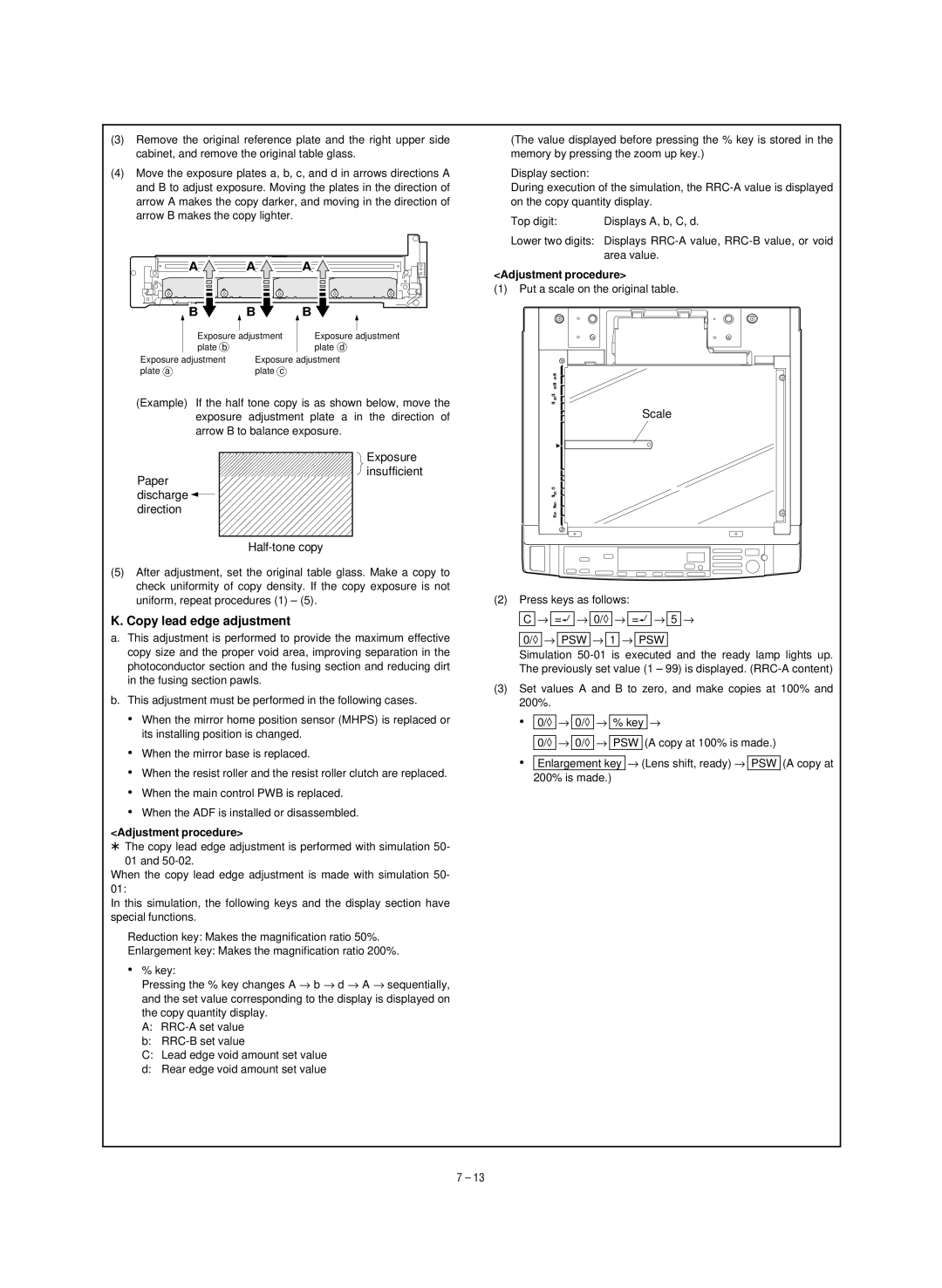
(1)Put a scale on the original table.
Scale
(2)Press keys as follows:
C → ë → 0/◊ → ë → 5 →
0/◊ → PSW → 1 → PSW
Simulation
(3)Set values A and B to zero, and make copies at 100% and 200%.
• 0/◊ → 0/◊ → % key →
0/◊ → 0/◊ → PSW (A copy at 100% is made.)
•Enlargement key → (Lens shift, ready) → PSW (A copy at 200% is made.)
7 – 13