(3) Details of image forming process
Step 1 (Main Charging)
By negative discharging of the main charger, uniform negative char- ges are applied to the OPC drum surface.
The OPC drum surface potential is controlled by the screen grid voltage to maintain the grid voltage at a constant level.
•When the drum surface potential is lower than the grid voltage, electric charges generated by discharging of the charger go through the screen grid to charge the drum surface potential until it becomes equal to the grid voltage.
•When the drum surface potential virtually reaches the grid potential level, electric charges generated by discharging of the charger flows through the electrode of the screen grid to the high voltage unit grid voltage output circuit, thus always maintaining the drum surface potential at a level virtually equal to the grid voltage.
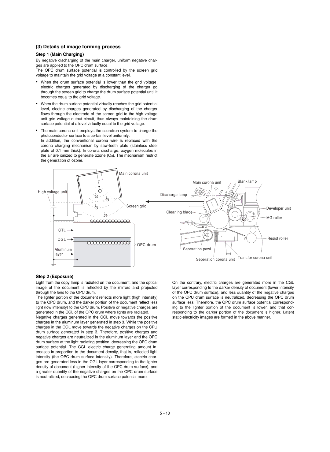
•The main corona unit employs the scorotron system to charge the photoconductor surface to a certain level uniformly.
In addition, the conventional corona wire is replaced with the corona charging mechanism by
Main corona unit
Main corona unit | Blank lamp |
High voltage unit
Discharge lamp
| Screen grid | Developer unit |
|
| |
|
| Cleaning blade |
|
| MG roller |
CTL |
|
|
CGL |
| Resist roller |
| OPC drum | Seperation pawl |
Aluminum |
| |
layer |
| Seperation corona unit Transfer corona unit |
|
|
Step 2 (Exposure)
Light from the copy lamp is radiated on the document, and the optical image of the document is reflected by the mirrors and projected through the lens to the OPC drum.
The lighter portion of the document reflects more light (high intensity) to the OPC drum, and the darker portion of the document reflect less light (low intensity) to the OPC drum. Positive or negative charges are generated in the CGL of the OPC drum where lights are radiated.
Negative charges generated in the CGL move towards the positive charges in the aluminum layer generated in step 3. While the positive charges in the CGL move towards the negative charges on the CPU drum surface generated in step 3. Therefore, positive charges and negative charges are neutralized in the aluminum layer and the OPC drum surface at the light radiating position, decreasing the OPC drum surface potential. The CGL electric charge generating amount in- creases in proportion to the document density, that is, reflected light intensity (the OPC drum surface intensity). Therefore, electric char- ges are generated less in the CGL layer corresponding to the lighter density of document (higher intensity of the OPC drum surface), and a greater quantity of the negative charges on the OPC drum surface is neutralized, decreasing the OPC drum surface potential more.
On the contrary, electric charges are generated more in the CGL layer corresponding to the darker density of document (lower intensity of the OPC drum surface), and less quantity of the negative charges on the CPU drum surface is neutralized, decreasing the OPC drum surface less. Therefore, the OPC drum surface potential correspond- ing to the lighter portion of the document is lower, and that cor- responding to the darker portion of the document is higher. Latent
5 – 10