3) Basic operations
(Cassette paper feed)
When the CPFC (cassette paper feed clutch) is turned on, the paper feed roller shaft, the paper feed roller, and the
Proccess | Main motor | |
unit | ||
| ||
Main drive unit | ||
Stirring roller |
| |
DV drive unit | Fuser unit | |
MG roller |
| |
Cleaner | Transport | |
unit | unit | |
PS roller | Paper exit | |
| ||
Multi manual | roller | |
| ||
insertion paper |
| |
feed unit |
| |
(Option) |
| |
Transport |
| |
roller(upper) |
| |
Transport roller(lower)
|
|
| Paper feed |
Paper feed |
| ||
| rive unit | ||
unit |
| ||
|
| ||
|
|
|
|
Paper feed unit
(3) Optical section
1. General description
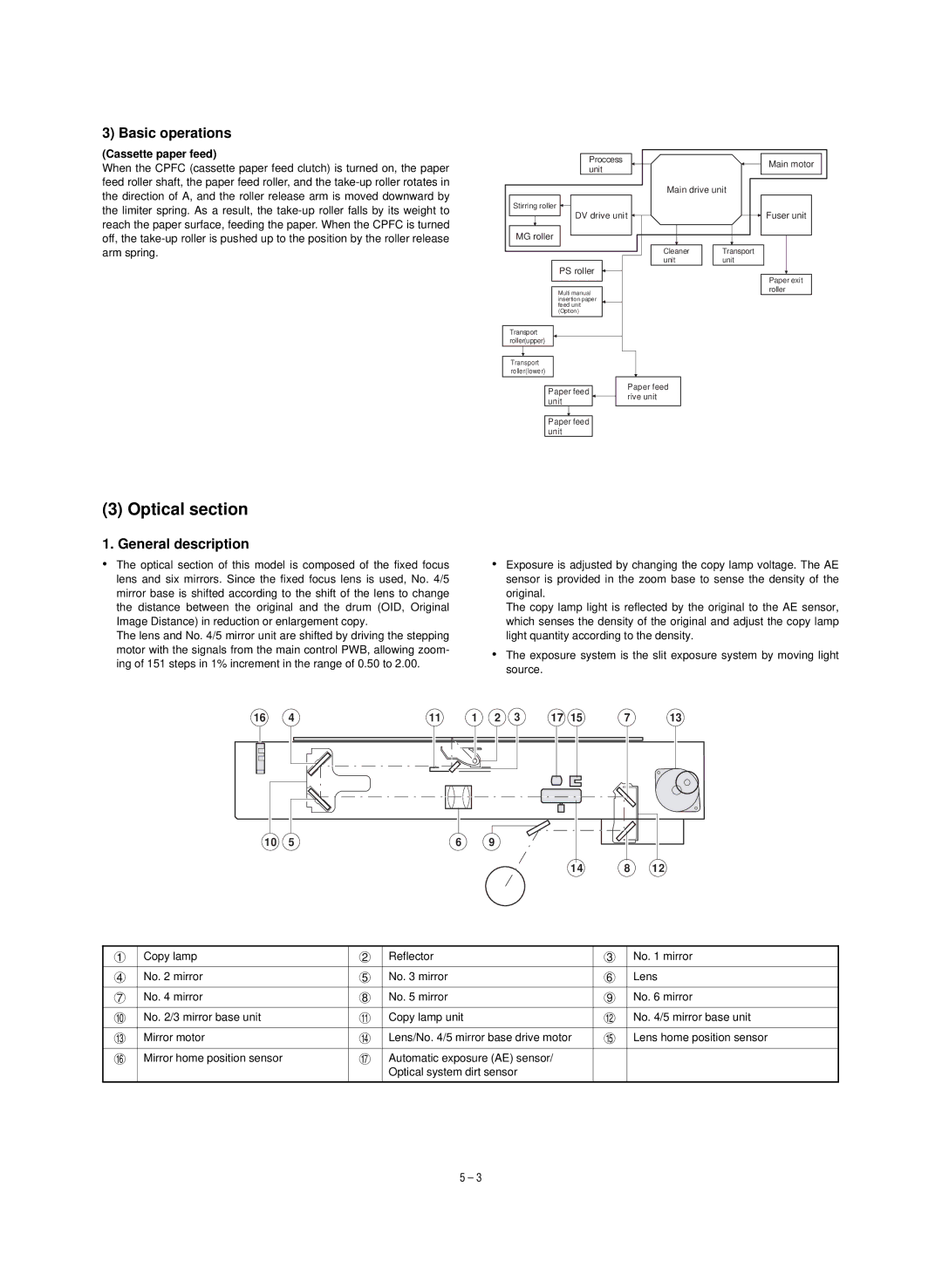
•The optical section of this model is composed of the fixed focus lens and six mirrors. Since the fixed focus lens is used, No. 4/5 mirror base is shifted according to the shift of the lens to change the distance between the original and the drum (OID, Original Image Distance) in reduction or enlargement copy.
The lens and No. 4/5 mirror unit are shifted by driving the stepping motor with the signals from the main control PWB, allowing zoom- ing of 151 steps in 1% increment in the range of 0.50 to 2.00.
•Exposure is adjusted by changing the copy lamp voltage. The AE sensor is provided in the zoom base to sense the density of the original.
The copy lamp light is reflected by the original to the AE sensor, which senses the density of the original and adjust the copy lamp light quantity according to the density.
•The exposure system is the slit exposure system by moving light source.
16 | 4 | 11 | 1 | 2 | 3 | 17 | 15 | 7 | 13 |
10 | 5 | 6 |
| 9 |
|
|
|
|
|
|
|
|
|
|
|
| 14 | 8 | 12 |
1 | Copy lamp | 2 | Reflector | 3 | No. 1 mirror |
|
|
|
|
|
|
4 | No. 2 mirror | 5 | No. 3 mirror | 6 | Lens |
|
|
|
|
|
|
7 | No. 4 mirror | 8 | No. 5 mirror | 9 | No. 6 mirror |
|
|
|
|
|
|
F | No. 2/3 mirror base unit | G | Copy lamp unit | H | No. 4/5 mirror base unit |
|
|
|
|
|
|
I | Mirror motor | J | Lens/No. 4/5 mirror base drive motor | K | Lens home position sensor |
|
|
|
|
|
|
L | Mirror home position sensor | M | Automatic exposure (AE) sensor/ |
|
|
|
|
| Optical system dirt sensor |
|
|
|
|
|
|
|
|
5 – 3
