Chapter 2 Getting Started
Implementing LVS
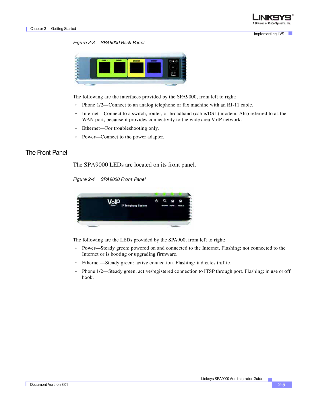
Figure 2-3 SPA9000 Back Panel
The following are the interfaces provided by the SPA9000, from left to right:
•Phone 1/2—Connect to an analog telephone or fax machine with an RJ-11 cable.
•Internet—Connect to a switch, router, or broadband (cable/DSL) modem. Also referred to as the WAN port, because it provides connectivity to the wide area VoIP network.
•Ethernet—For troubleshooting only.
•Power—Connect to the power adapter.
The Front Panel
The SPA9000 LEDs are located on its front panel.
Figure 2-4 SPA9000 Front Panel
The following are the LEDs provided by the SPA900, from left to right:
•Power—Steady green: powered on and connected to the Internet. Flashing: not connected to the Internet or is booting or upgrading firmware.
•Ethernet—Steady green: active connection. Flashing: indicates traffic.
•Phone 1/2—Steady green: active/registered connection to ITSP through port. Flashing: in use or off hook.
| | Linksys SPA9000 Administrator Guide | | |
| | |
| Document Version 3.01 | | | 2-5 | |
| | | |