Field Replaceable Units
FRU Removal and Replacement
Perform the following steps to replace or install additional memory DIMMs:
1.Open the left side panel of the workstation as shown in the section “Opening the Left Side Panel.”
Figure 4-42. System Board View
B2000
System Label
Power
Supply
DIMM connectors
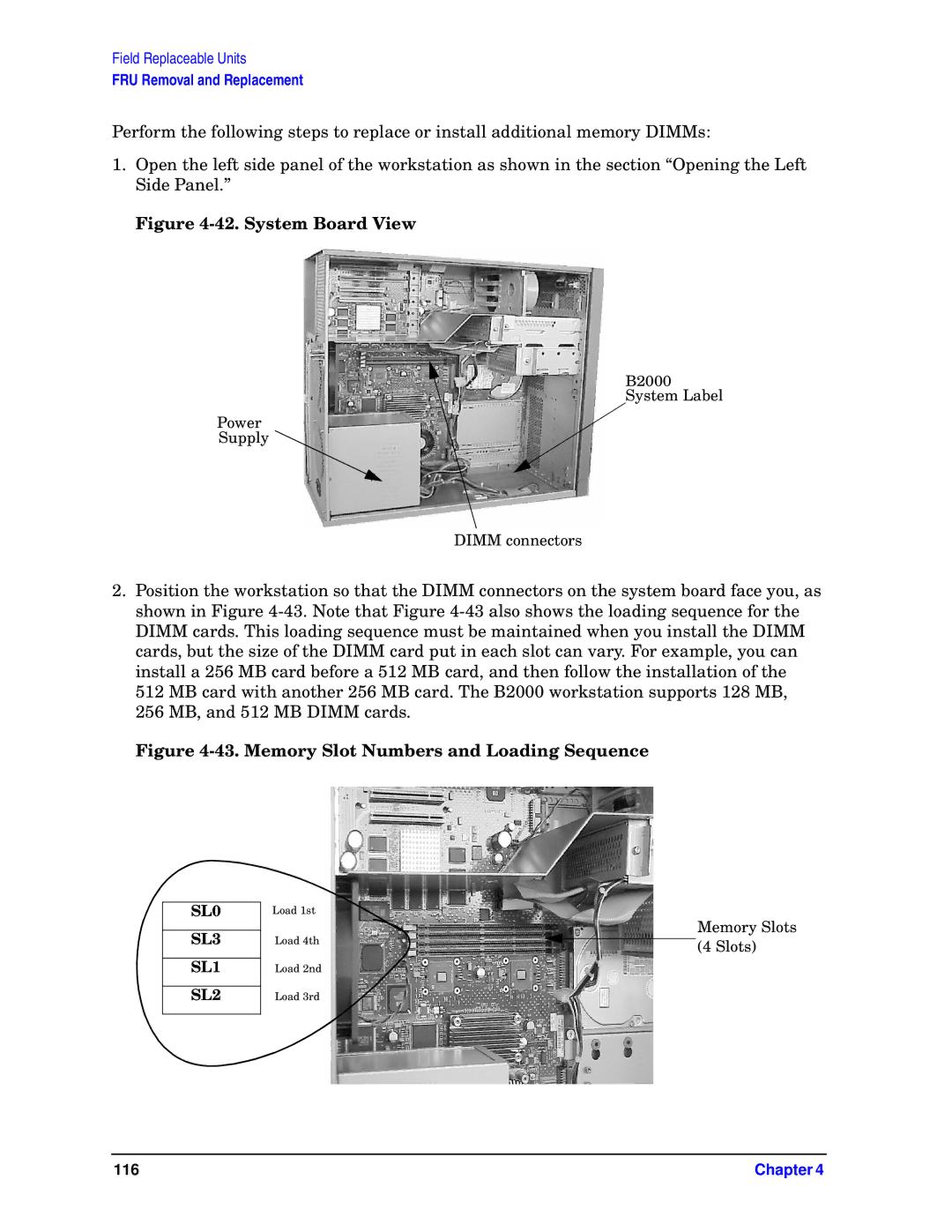
2.Position the workstation so that the DIMM connectors on the system board face you, as shown in Figure
512 MB card with another 256 MB card. The B2000 workstation supports 128 MB, 256 MB, and 512 MB DIMM cards.
Figure 4-43. Memory Slot Numbers and Loading Sequence
SL0
SL3
SL1
SL2
Load 1st
Load 4th
Load 2nd
Load 3rd
Memory Slots (4 Slots)
116 | Chapter 4 |
