Field Replaceable Units
Chapter Overview
Tools Required
Use the following tools to remove or replace FRUs in the B2000 workstation:
•Torx
•
•
•ESD equipment (see “Electrostatic Discharge (ESD) Precautions” on page 177)
Exploded View Diagram
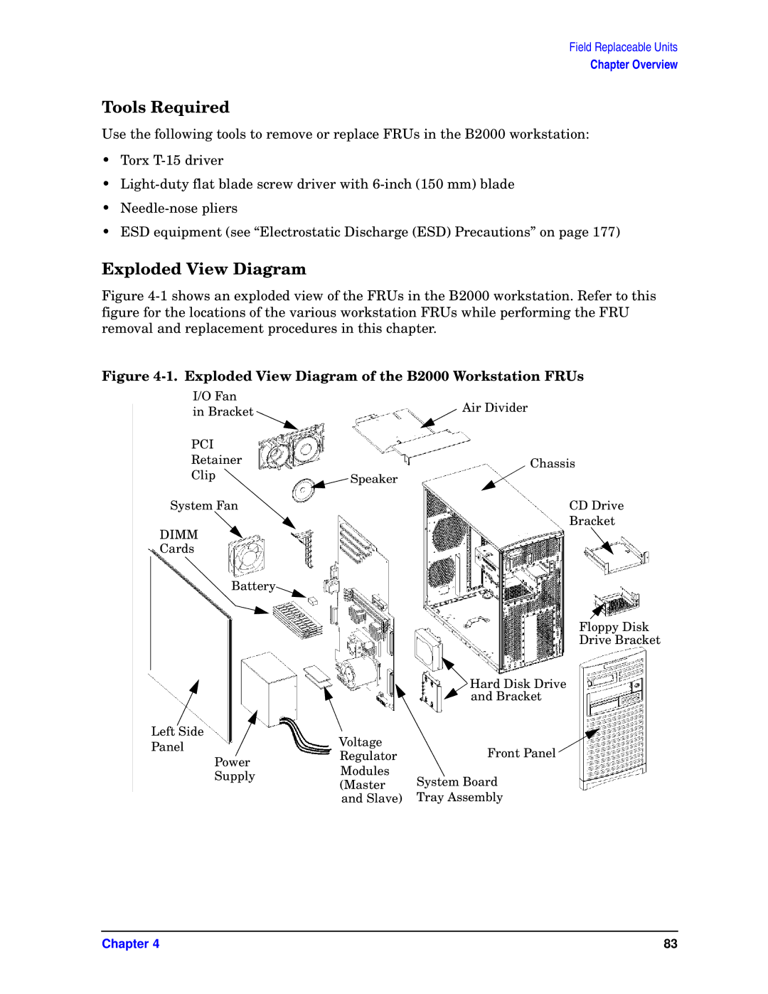
Figure 4-1 shows an exploded view of the FRUs in the B2000 workstation. Refer to this figure for the locations of the various workstation FRUs while performing the FRU removal and replacement procedures in this chapter.
Figure 4-1. Exploded View Diagram of the B2000 Workstation FRUs
I/O Fan
in Bracket | Air Divider |
| |
PCI |
|
Retainer | Chassis |
Clip | Speaker |
| |
System Fan | CD Drive |
DIMM | Bracket |
| |
Cards |
|
Battery![]()
Floppy Disk
Drive Bracket
|
|
| Hard Disk Drive |
|
|
| and Bracket |
Left Side |
| Voltage |
|
Panel |
| Front Panel | |
| Regulator | ||
| Power | ||
| Modules |
| |
| Supply | System Board | |
| (Master | ||
|
| ||
|
| and Slave) | Tray Assembly |
Chapter 4 | 83 |