A
4 – Managing Switches Managing Switch Stacks
4.8
Managing Switch Stacks
SANsurfer Switch Manager recognizes switches as a stack if they are connected by their high speed stacking ports. The switch management application will
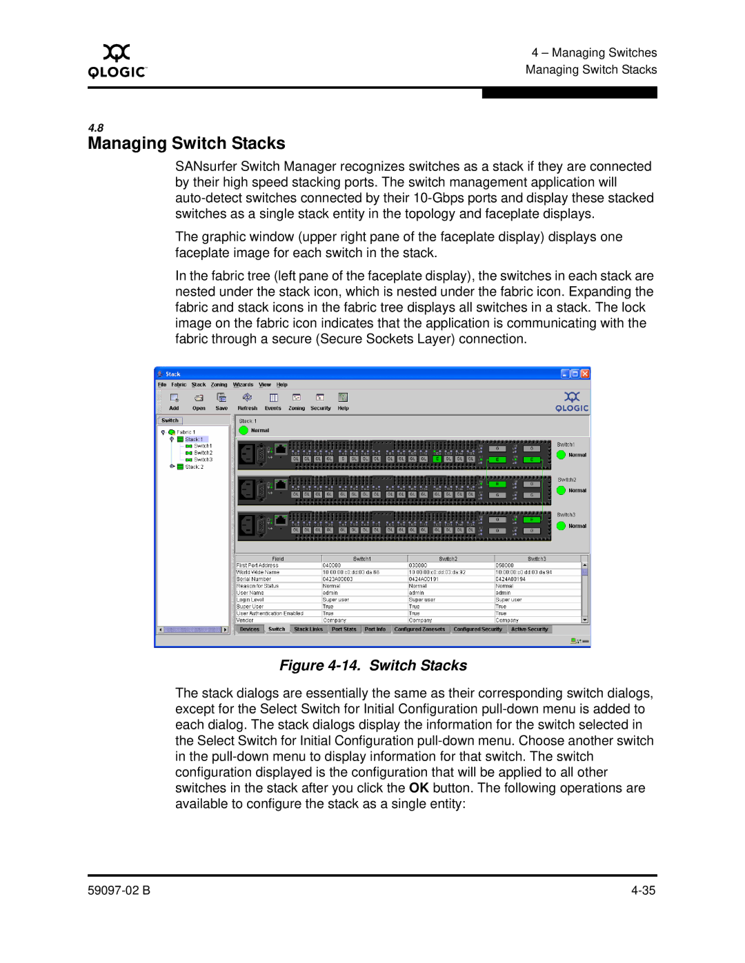
The graphic window (upper right pane of the faceplate display) displays one faceplate image for each switch in the stack.
In the fabric tree (left pane of the faceplate display), the switches in each stack are nested under the stack icon, which is nested under the fabric icon. Expanding the fabric and stack icons in the fabric tree displays all switches in a stack. The lock image on the fabric icon indicates that the application is communicating with the fabric through a secure (Secure Sockets Layer) connection.
Figure 4-14. Switch Stacks
The stack dialogs are essentially the same as their corresponding switch dialogs, except for the Select Switch for Initial Configuration
