Chapter 5: Troubleshooting
General Troubleshooting
Acquisition board status LEDs
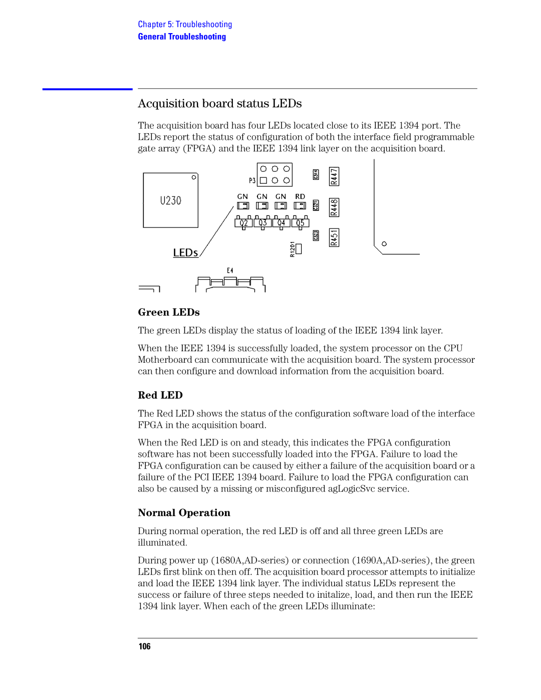
The acquisition board has four LEDs located close to its IEEE 1394 port. The LEDs report the status of configuration of both the interface field programmable gate array (FPGA) and the IEEE 1394 link layer on the acquisition board.
Green LEDs
The green LEDs display the status of loading of the IEEE 1394 link layer.
When the IEEE 1394 is successfully loaded, the system processor on the CPU Motherboard can communicate with the acquisition board. The system processor can then configure and download information from the acquisition board.
Red LED
The Red LED shows the status of the configuration software load of the interface FPGA in the acquisition board.
When the Red LED is on and steady, this indicates the FPGA configuration software has not been successfully loaded into the FPGA. Failure to load the FPGA configuration can be caused by either a failure of the acquisition board or a failure of the PCI IEEE 1394 board. Failure to load the FPGA configuration can also be caused by a missing or misconfigured agLogicSvc service.
Normal Operation
During normal operation, the red LED is off and all three green LEDs are illuminated.
During power up
