Agilent Technologies 1680/90-Series Logic Analyzer
Agilent 1680/90-Series Logic Analyzer-At a Glance
Features
Service Strategy
This Book
Contents
To test the multiple-clock state acquisition
Troubleshooting
Theory of Operation
General Information
Accessories Supplied Agilent Part Number
Accessories
Characteristics
Specifications
Full Channel
Channel Count
Probes
Dimensions
Equipment Required
Recommended Test Equipment
Preparing for Use
To inspect the logic analyzer
Power Requirements
To connect the 1690A,AD-series logic analyzer to a host PC
To apply power
To clean the logic analyzer
To start the user interface
To test the logic analyzer
Testing Performance
Test Interval
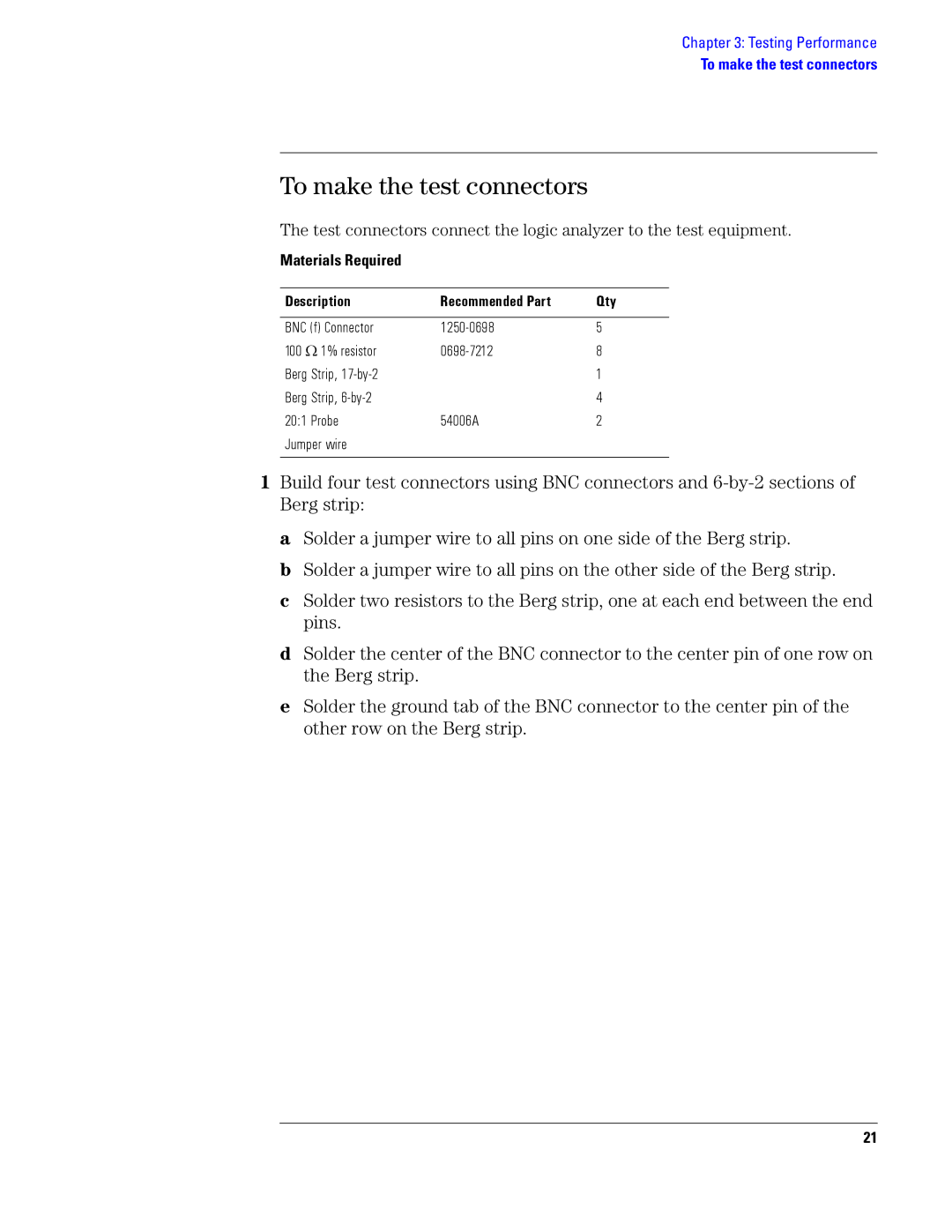
To make the test connectors
Materials Required Description
Qty
To make the test connectors
Set up the test equipment
To set up the test equipment and the logic analyzer
Equipment Required Critical Specifications
Pulse Generator Setup Timebase Channel Trigger
Set up the 1680A,AD-series logic analyzer
Oscilloscope Setup Acquisition Display Trigger Shift ∆ Time
Channel Define meas
To perform the logic analyzer self-tests
Set up the 1690A,AD-series logic analyzer
Set the reporting level
Click Close to close the Analysis System Self Tests dialog
To test the threshold accuracy
Set up the equipment
Connect and configure the logic analyzer
Test the ECL Threshold
Test the 0 V User Threshold
Test the next pod
To set up the logic analyzer for the state mode tests
To set up the logic analyzer for the state mode tests
Click OK to close the Value dialog
To set up the logic analyzer for the state mode tests
To test the single-clock, single-edge, state acquisition
Channel 1 Output
Combinations Channel 2 Output
Combination Channel 2 Output
Verify the test signal
Setup/Hold Combinations Test Sample Position Times Window
Check the setup/hold combination
To test the single-clock, single-edge, state acquisition
Following clock configurations will be used in steps 4, 5,
To test the single-clock, single-edge, state acquisition
Following clock configurations will be used in steps 9, 10
To test the single-clock, single-edge, state acquisition
Test the next channels 1680/81A,AD and 1690/91A,AD
To test the multiple-clock state acquisition
1680A, AD or 1690A, AD only
1682A, AD or 1692A, AD only
Verify the test signal
2.0 ns 4.50 ns +3.0 ns
To test the multiple-clock state acquisition
To test the multiple-clock state acquisition
Enable the pulse generator channel 1 Comp with the LED on
Test the next channels 1680/81A, AD and 1690/91A, AD
To test the single-clock, multiple-edge, state acquisition
Modify the following pulse generator settings
1680A,AD or 1690A,AD only Pod 2, channel
1682A,AD or 1692A,AD only Pod 1, channel
Verify the test signal
Check the setup/hold with single clock, multiple clock edges
To test the single-clock, multiple-edge, state acquisition
Following clock configurations will be used in steps 3, 4,
To test the single-clock, multiple-edge, state acquisition
Test the next channels 1680/81A,AD and 1690/91A,AD
To test the time interval accuracy
Function Generator Setup
To test the time interval accuracy
Click the Run icon to fill acquisition memory
Acquire and verify the test data
To test the time interval accuracy
Performance Test Record
Test Settings Results Self-Tests
Threshold
Accuracy
Performance Test Record Settings Results
Edge Acquisition
Multiple-Clock Multiple-Edge Acquisition
Time Interval
Performance Test Record Settings Results Single-Clock
Performance Test Record
Calibrating and Adjusting
Logic analyzer calibration
Troubleshooting
To install the fan guard
To use the flowcharts
Start
Troubleshooting the Agilent 1680A,AD-series
Replace Power supply
Are both instrument
Yes Possible problem with LCD display, inverter, or cables
Does the blue
Uninstall, then reinstall Agilent Logic Analyzer application
Possible problem with
To test the power supply voltages
To check the power-up tests
Pin Voltage
Power Supply Voltages
To test the LCD display signals
To test disk drive voltages
Equipment Required Critical Specification
Disk Drive Voltages Pin No Signal
To verify the CD-ROM
Disk Drive Voltages Pin Signals Pin No
To reinstall the operating system
To recover the operating system
Problems with the Operating System
Troubleshooting the Agilent 1690A,AD-series
Yes Is the power cord Connected?
Consult host PC
Test pass?
Task Manager
To verify connectivity
100
Device Manager
101
102
General Troubleshooting
To run the self-tests
103
104
105
106
Acquisition board status LEDs
107
To test the logic analyzer probe cables
108
109
110
To check the BNC Trigger input/output signals
111
On the DC source, enter a voltage setting of 3.000
Digital Multimeter
To test the auxiliary power
005% accuracy
112
113
Replacing Assemblies
Prepare the instrument for disassembly
1680A,AD-series disassembly/assembly
To remove the chassis from the sleeve
114
115
To remove the acquisition board
116
117
To remove the power supply
118
To remove the hard disk drive
119
To remove the CD-ROM drive assembly
120
To remove the flexible disk drive
121
122
To remove the PCI boards
123
To remove the motherboard
124
Transfer the I/O panel to the replacement board
125
126
To remove the front panel assembly
127
Reverse this procedure to install the front panel assembly
128
To disassemble the front panel assembly
129
To remove the distribution board
130
To remove the inverter board
131
To remove the fans
132
To remove the cable tray
133
1690A,AD-series disassembly/assembly
134
To remove the fascia
135
Remove the fascia away from the front panel
136
137
To remove the deck
138
139
140
To remove the line filter
141
To remove the front panel and front frame
142
143
Replaceable Parts
144
Replaceable Parts Ordering
Replaceable Parts List
See Also
145
Exploded View
Replaceable Parts Ref. Des
Agilent 1680A,AD-Series Replaceable Parts
Exchange Assemblies
147
148
0515-0372
149
150
151
Front Panel Assembly
152
Exploded View
154
Agilent 1690A,AD-Series Replaceable Parts
155
156
157
Power Cables and Plug Configurations
Plug Type Cable Plug Description Length Color Country In/cm
158
159
Theory of Operation
Block-Level Theory
Agilent 1680A,AD-Series Logic Analyzer Block Diagram 160
161
Agilent 1680A,AD-series Logic Analyzer Theory
Logic Acquisition Board Block Diagram
Power Supply
Acquisition Board
162
163
164
Power Distribution Board
Front Panel Board
165
166
Agilent 1690A,AD-series Logic Analyzer Theory
Self-Tests Descriptions
Power-up Self-Tests 1680A,AD-series
Connectivity Tests 1690A,AD-series
167
168
Acquisition Board Self Tests
169
Logic Analyzer Self-Tests
170
171
172
Manual Part Number Technology Licenses