Chapter 5: Troubleshooting
General Troubleshooting
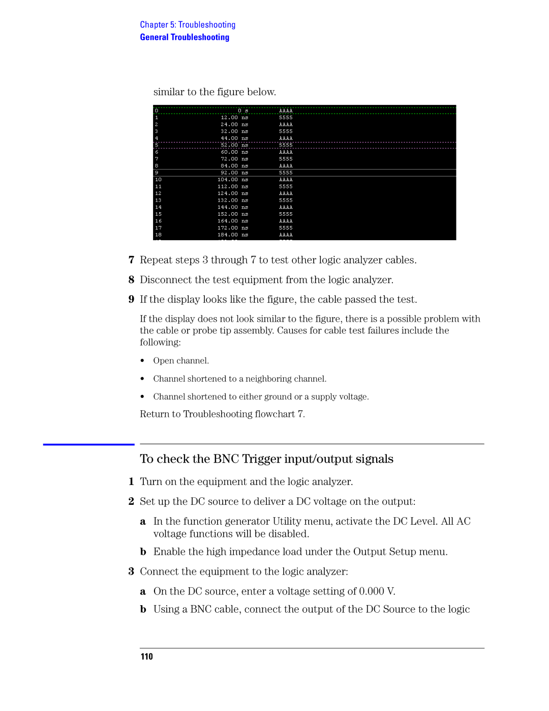
similar to the figure below.
7Repeat steps 3 through 7 to test other logic analyzer cables.
8Disconnect the test equipment from the logic analyzer.
9If the display looks like the figure, the cable passed the test.
If the display does not look similar to the figure, there is a possible problem with the cable or probe tip assembly. Causes for cable test failures include the following:
•Open channel.
•Channel shortened to a neighboring channel.
•Channel shortened to either ground or a supply voltage.
Return to Troubleshooting flowchart 7.
To check the BNC Trigger input/output signals
1Turn on the equipment and the logic analyzer.
2Set up the DC source to deliver a DC voltage on the output:
a In the function generator Utility menu, activate the DC Level. All AC voltage functions will be disabled.
b Enable the high impedance load under the Output Setup menu.
3Connect the equipment to the logic analyzer:
a On the DC source, enter a voltage setting of 0.000 V.
b Using a BNC cable, connect the output of the DC Source to the logic