Chapter 3: Testing Performance
To test the
Verify the test signal
1Check the clock period. Using the oscilloscope, verify that the
a Enable the pulse generator channel 1, channel 2, and trigger outputs (LED off).
b In the oscilloscope Timebase menu, select Scale: 2.000 ns/div.
c In the oscilloscope Timebase menu, select Position. Using the oscilloscope knob, position the clock waveform so that a rising edge appears at the left of the display.
d On the oscilloscope, select [Shift] + width: channel 2, then select [Enter] to display the
e On the oscilloscope, select [Shift] - width: channel 2, then select [Enter] (- width(2)). If the negative pulse width is less than or equal to 5.000 ns but greater than 4.900 ns, go to step 2.
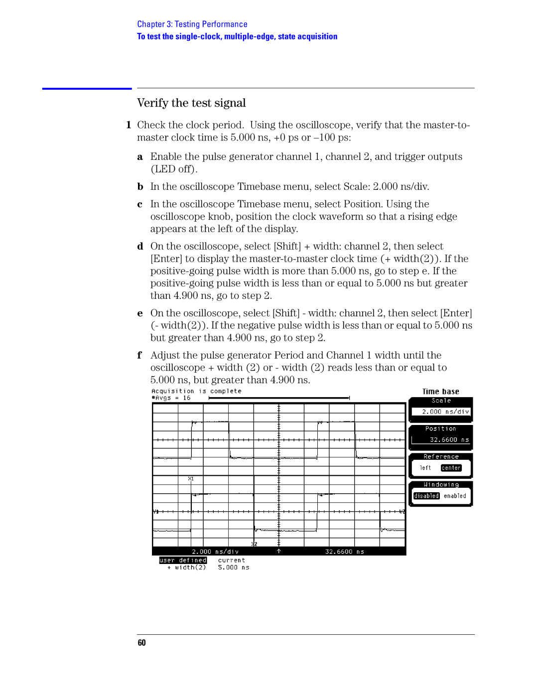
f Adjust the pulse generator Period and Channel 1 width until the oscilloscope + width (2) or - width (2) reads less than or equal to 5.000 ns, but greater than 4.900 ns.
60