Service Guide
Agilent Technologies 1680/90-Series Logic Analyzer
Features
The Agilent 1680/90-Series Logic Analyzer-At a Glance
Service Strategy
In This Book
To make the test connectors
Contents
3 Testing Performance
The Agilent 1680/90-Series Logic Analyzer-At a Glance
4 Calibrating and Adjusting
Contents
To set up the logic analyzer for the state mode tests
To test the threshold accuracy
Troubleshooting the Agilent 1680A,AD-series
Contents
5 Troubleshooting
Troubleshooting the Agilent 1690A,AD-series
8 Theory of Operation
Contents
1690A,AD-series disassembly/assembly
Agilent 1680A,AD-series Logic Analyzer Theory
General Information
Accessories
Accessories Available
Characteristics
Specifications
Setup/Hold Time
Probes
Auxiliary Power
Operating Environment for indoor use only
1680A,AD-Series 1690A,AD-Series
Dimensions
Chapter 1 General Information
Equipment Required
Recommended Test Equipment
Chapter 1 General Information
Equipment
Preparing for Use
Storage
Power Requirements
Operating Environment
To inspect the logic analyzer
1 Connect the power cord to the instrument and to the power source
To apply power
To connect the 1690A,AD-series logic analyzer to a host PC
2 Turn on the power switch located on the front panel
To start the user interface
To clean the logic analyzer
To test the logic analyzer
Testing Performance
Test Interval
The Logic Analyzer Interface
Test Strategy
Performance Test Record
To make the test connectors
a Solder a jumper wire to all pins on one side of the Berg strip
To set up the test equipment and the logic analyzer
Set up the test equipment
Set up the 1680A,AD-series logic analyzer
Chapter 3 Testing Performance
Set up the 1690A,AD-series logic analyzer
To perform the logic analyzer self-tests
To set up the test equipment and the logic analyzer
3 Set the reporting level
Chapter 3 Testing Performance
To set up the test equipment and the logic analyzer
4 Select the tests you want to run 5 Click Start
To set up the test equipment and the logic analyzer
To reset the self-test options, click Reset
Chapter 3 Testing Performance
6 Click Close to close the Analysis System Self Tests dialog
Set up the equipment
To test the threshold accuracy
Connect and configure the logic analyzer
Test the ECL Threshold
Test the 0 V User Threshold
Test the next pod
To set up the logic analyzer for the state mode tests
3 Configure the trigger according to your logic analyzer
select the M1 marker c In the Position box, select Value
i Click OK to close the Value dialog
Connect and configure the logic analyzer
To test the single-clock, single-edge, state acquisition
Set up the equipment
To test the single-clock, single-edge, state acquisition
Chapter 3 Testing Performance
Testing
Connect the 1680/81/90/91A,AD Logic Analyzer to the Pulse Generator
1682A,AD or 1692A,AD only
Pod 1 clock/data channel Clk
Verify the test signal
Check the setup/hold combination
3 Select the logic analyzer sample positions
Chapter 3 Testing Performance
a In the Analyzer Setup dialog, click on the Sampling tab
The following clock configurations will be used in steps 4, 5, and
d Click OK to close the Sample Positions dialog
e Click OK to close the Analyzer Setup dialog 5 Verify the test data
then select Enter to display the setup time ∆ Time1-2
e Click OK to close the Analyzer Setup dialog 10 Verify the test data
Chapter 3 Testing Performance
Test the next channels 1680/81A,AD and 1690/91A,AD
To test the single-clock, single-edge, state acquisition
1 If you have not already done so, do the following procedures
To test the multiple-clock state acquisition
Set up the equipment
2 Increase the pulse generator channel 2 width to 3.000 ns
Connect to 8133A
Connect and configure the logic analyzer
1680A, AD or 1690A, AD only
Channel 2 Output
1682A, AD or 1692A, AD only
Clock/data channel for Pod 1, 2, 3, and 4 Clk 1, Clk 2, Clk 3, Clk
Verify the test signal
Check the setup/hold with single clock edges, multiple clocks
3 Select the clocks to be tested
d Connect all clock channels to the pulse generator channel 1 output
Page
Test the next channels 1680/81A, AD and 1690/91A, AD
Set up the equipment
To test the single-clock, multiple-edge, state acquisition
Connect the 1680/81/90/91A,AD Logic Analyzer to the Pulse Generator
Connect and configure the logic analyzer
Testing
Connect to 8133A
1Pod 1, channel 3 Pod 2, channel 3 Pod 3, channel 3 Pod 4, channel
Verify the test signal
Check the setup/hold with single clock, multiple clock edges
Page
The following clock configurations will be used in steps 3, 4, and
The test passes when the logic analyzer finds all occurrences of the patterns programmed into the Markers. If the test passes, record a Pass in the performance test record under single-clock single-edge next to the clock and edge being tested
Test the next channels 1680/81A,AD and 1690/91A,AD
Chapter 3 Testing Performance
To test the single-clock, multiple-edge, state acquisition
Set up the equipment
To test the time interval accuracy
Connect and configure the logic analyzer
3 Set up the function generator according to the following table
d Select an Acquisition Depth of 256K
Acquire and verify the test data
f Click OK to close the Value dialog
Settings
Performance Test Record
Chapter 3 Testing Performance
Performance Test Record
Chapter 3 Testing Performance
Settings
Performance Test Record continued
Performance Test Record
Chapter 3 Testing Performance
Settings
Performance Test Record continued
Chapter 3 Testing Performance
Performance Test Record
Calibrating and Adjusting
Logic analyzer calibration
Chapter 4 Calibrating and Adjusting
Troubleshooting
a Position the chassis so the handle side is up
To install the fan guard
2 Install the fan guard onto the chassis
b Slide the fan guard onto the chassis over the fans
To use the flowcharts
c Install the optional screws as shown
Chapter 5 Troubleshooting
Troubleshooting the Agilent 1680A,AD-series
Chapter 5 Troubleshooting
Troubleshooting the Agilent 1680A,AD-series
Chapter 5 Troubleshooting
Troubleshooting the Agilent 1680A,AD-series
Chapter 5 Troubleshooting
Troubleshooting the Agilent 1680A,AD-series
Chapter 5 Troubleshooting
Troubleshooting the Agilent 1680A,AD-series
Chapter 5 Troubleshooting
Troubleshooting the Agilent 1680A,AD-series
Chapter 5 Troubleshooting
Troubleshooting the Agilent 1680A,AD-series
To check the power-up tests
To test the power supply voltages
5 Using DVM, measure the power supply voltages
To test the LCD display signals
To test disk drive voltages
6 Troubleshoot a flexible disk drive. a Apply power to the instrument
To verify the CD-ROM
To reinstall the operating system
To recover the operating system
Problems running the Application Software
Problems with the Operating System
Chapter 5 Troubleshooting
Troubleshooting the Agilent 1690A,AD-series
Chapter 5 Troubleshooting
Troubleshooting the Agilent 1690A,AD-series
Chapter 5 Troubleshooting
Troubleshooting the Agilent 1690A,AD-series
Chapter 5 Troubleshooting
Troubleshooting the Agilent 1690A,AD-series
To verify connectivity
Task Manager
Device Manager
To test the power supply voltages
a Click on the Start button in the task bar, then select Shut Down
Chapter 5 Troubleshooting
Troubleshooting the Agilent 1690A,AD-series
Chapter 5 Troubleshooting
General Troubleshooting
To run the self-tests
General Troubleshooting
6 Set the reporting level
Chapter 5 Troubleshooting
General Troubleshooting
7 Select the tests you want to run 8 Click Start
9 Click Close to close the Analysis System Self Tests dialog
Red LED
Acquisition board status LEDs
Green LEDs
Normal Operation
To test the logic analyzer probe cables
1 Turn on the equipment and the logic analyzer
COMP Disabled LED Off
5 Configure the pod under test
To check the BNC Trigger input/output signals
Return to Troubleshooting flowchart
analyzer Trigger In BNC
To test the auxiliary power
Recommended
Replacing Assemblies
Prepare the instrument for disassembly
1680A,AD-series disassembly/assembly
To remove the chassis from the sleeve
To remove the acquisition board
Steps to remove probe shroud from acquisition board
To remove the power supply
To remove the hard disk drive
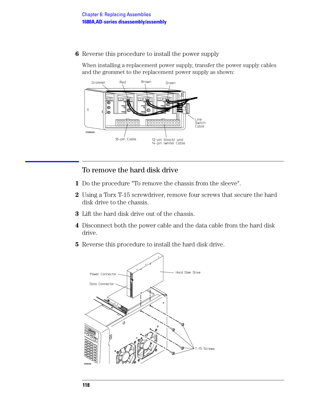
To remove the CD-ROM drive assembly
To remove the flexible disk drive
5 Reverse this procedure to install the flexible disk drive
PCI display board slot slot covers slot 3 and slot
To remove the PCI boards
PCI IEEE 1394 board slot 2, closest to the CD-ROM drive
PCI IEEE 1394 board IEEE 1394 cable PCI display board video cable
power cable from connector CN1 CPU fan cable
To remove the motherboard
audio cable from connector CD
Transfer the I/O panel to the replacement board
5 Install 6 hex studs onto the motherboard ports and tighten
on/off cable accessed from the bottom of the chassis keyboard cable
To remove the front panel assembly
inverter cable
6 Reverse this procedure to install the front panel assembly
Remove the front panel circuit board
To disassemble the front panel assembly
Remove the on/off switch
Remove the LCD display
To remove the distribution board
To remove the inverter board
To remove the fans
To remove the cable tray
1690A,AD-series disassembly/assembly
Prepare the instrument for disassembly
To remove the chassis from the sleeve
To remove the fascia
4 Remove the fascia away from the front panel
1 Do the following procedures
To remove the acquisition board
To remove the deck
To remove the power supply
To remove the distribution board
To remove the fans
To remove the line filter
To remove the front panel and front frame
1690A,AD-series disassembly/assembly
Chapter 6 Replacing Assemblies
Replaceable Parts
Parts not listed
Parts listed
Replaceable Parts Ordering
Direct mail order system
Replaceable Parts List
Exchange Assemblies
Chapter 7 Replaceable Parts
Exploded View
Exploded view of the Agilent 1680A,AD-series logic analyzer
Replaceable Parts
Agilent 1680A,AD-Series Replaceable Parts
Chapter 7 Replaceable Parts
Ref. Des
M4.0 x 0.70 8 mm T20 PH power supply to
Replacement Pod Grounds - 5” Qty
CD-ROM drive assembly to chassis, sleeve to
Chapter 7 Replaceable Parts
Ref. Des
Chapter 7 Replaceable Parts
Replaceable Parts
Description
Chapter 7 Replaceable Parts
assembly, IEEE 1394 cable to chassis
Power Supply Cable 14- and 10- pin power supply
Replaceable Parts
Replaceable Parts
Front Panel Assembly
Chapter 7 Replaceable Parts
Ref. Des
Ref. Des
Chapter 7 Replaceable Parts
Replaceable Parts
Description
Chapter 7 Replaceable Parts
Exploded View
Exploded view of the Agilent 1690A,AD-series logic analyzer
Replaceable Parts
Agilent 1690A,AD-Series Replaceable Parts
Chapter 7 Replaceable Parts
Ref. Des
Chapter 7 Replaceable Parts
Fascia Assembly includes the following
Hex Nut acquisition board BNC connectors to
Replaceable Parts
Replaceable Parts
Power Supply On/Off Cable power supply to
Chapter 7 Replaceable Parts
Ref. Des
Plug Type
Power Cables and Plug Configurations
Chapter 7 Replaceable Parts
Cable
Cable
Chapter 7 Replaceable Parts
Plug Type
Plug Description
Theory of Operation
Agilent 1680A,AD-Series Logic Analyzer Block Diagram
Block-Level Theory
Chapter 8 Theory of Operation
Agilent 1680A,AD-series Logic Analyzer Theory
Acquisition Board
Power Supply
Logic Acquisition Board Block Diagram
Comparators. Two 9-channel comparators interpret the incoming data and clock signals as either high or low, depending on where the user-programmable threshold is set. The threshold voltage of each pod is individually programmed, and the voltage selected applies to the clock channel as well as the data channels of each pod
A field programmable gate array FPGA bridges the 1394 interface to the rest of the acquisition board components. It also serves as the memory controller for the acquisition memory
Power Distribution Board
Front Panel Board
Power Distribution Board
Agilent 1690A,AD-series Logic Analyzer Theory
Power Supply
Acquisition Board
Self-Tests Descriptions
Power-up Self-Tests 1680A,AD-series
Connectivity Tests 1690A,AD-series
Acquisition Board Self Tests
Logic Analyzer Self-Tests
Chapter 8 Theory of Operation
Self-Tests Descriptions
configured to take a simple measurement. Test data is then created at the comparators and an acquisition taken. The resulting data is then downloaded and compared with known values
Chapter 8 Theory of Operation
Self-Tests Descriptions
Notices
Warranty
Safety Notices
Manual Part Number