Chapter 7 NPE-G1 and NPE-G2 Installation and Configuration Information

Removing the Network Processing Engine

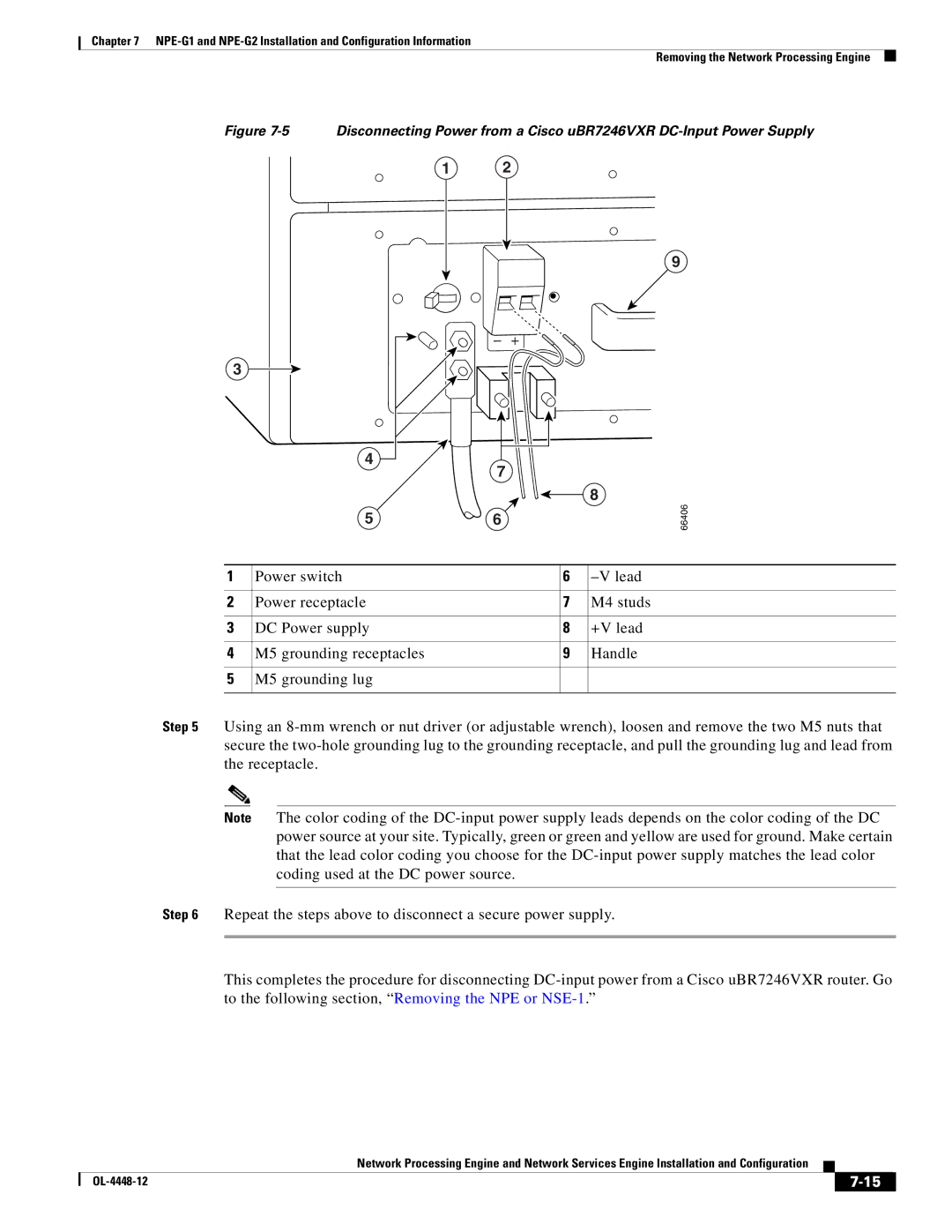
Figure 7-5 Disconnecting Power from a Cisco uBR7246VXR DC-Input Power Supply

1 2

9

3

4

7

8

5

6

66406

1

Power switch

6

–V lead


2

Power receptacle

7

M4 studs


3

DC Power supply

8

+V lead


4

M5 grounding receptacles

9

Handle


5

M5 grounding lug


Step 5 Using an 8-mm wrench or nut driver (or adjustable wrench), loosen and remove the two M5 nuts that secure the two-hole grounding lug to the grounding receptacle, and pull the grounding lug and lead from the receptacle.

Note The color coding of the DC-input power supply leads depends on the color coding of the DC power source at your site. Typically, green or green and yellow are used for ground. Make certain that the lead color coding you choose for the DC-input power supply matches the lead color coding used at the DC power source.

Step 6 Repeat the steps above to disconnect a secure power supply.

This completes the procedure for disconnecting DC-input power from a Cisco uBR7246VXR router. Go to the following section, “Removing the NPE or NSE-1.”

Network Processing Engine and Network Services Engine Installation and Configuration


OL-4448-12

7-15


Page 101
Image 101
Cisco Systems NPE-175, NPE-225 manual 66406