Chapter 10 Configuration Tasks and Troubleshooting Information
Removing and Replacing an
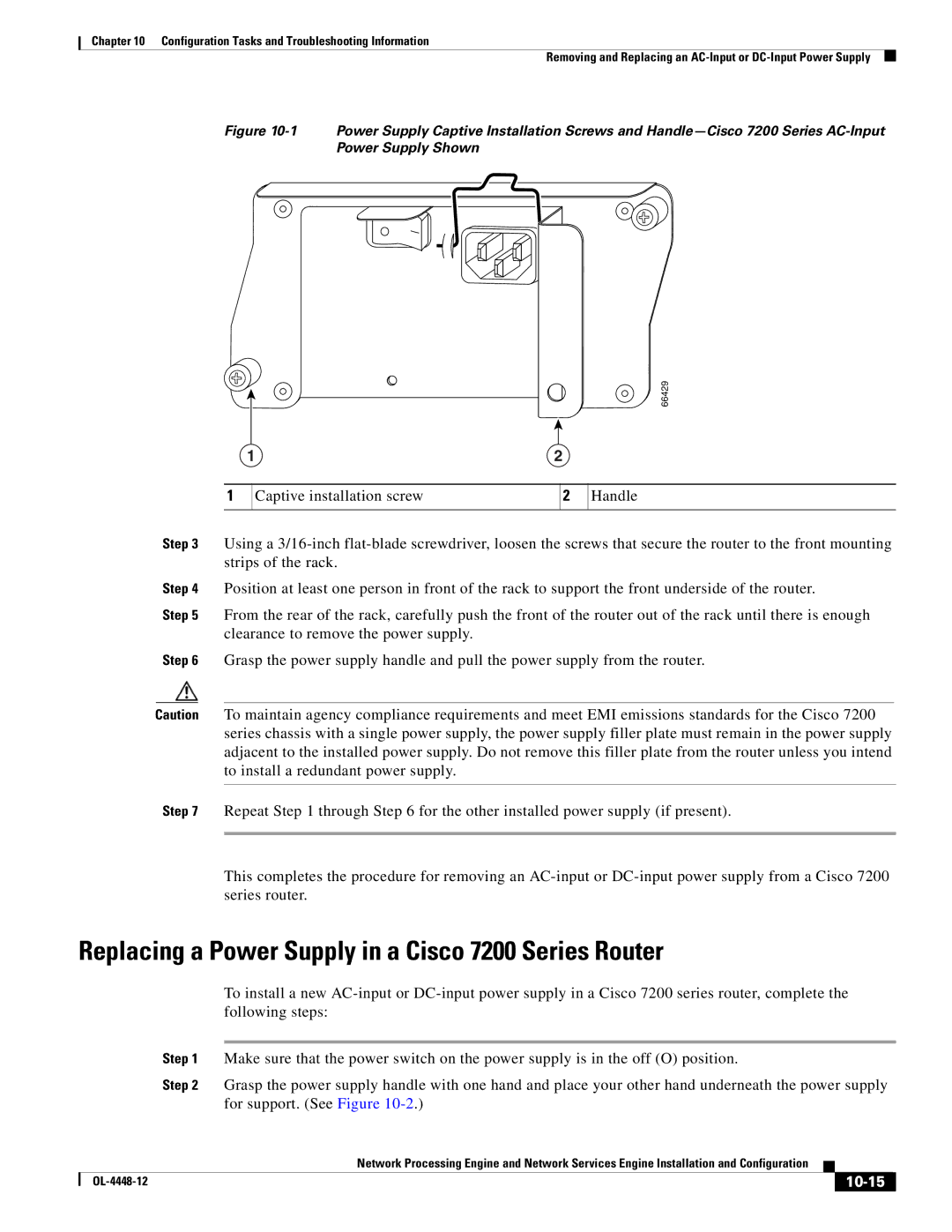
Figure 10-1 Power Supply Captive Installation Screws and Handle—Cisco 7200 Series AC-Input Power Supply Shown
66429
1 | 2 |
1
Captive installation screw
2
Handle
Step 3 Using a
Step 4 Position at least one person in front of the rack to support the front underside of the router.
Step 5 From the rear of the rack, carefully push the front of the router out of the rack until there is enough clearance to remove the power supply.
Step 6 Grasp the power supply handle and pull the power supply from the router.
Caution To maintain agency compliance requirements and meet EMI emissions standards for the Cisco 7200 series chassis with a single power supply, the power supply filler plate must remain in the power supply adjacent to the installed power supply. Do not remove this filler plate from the router unless you intend to install a redundant power supply.
Step 7 Repeat Step 1 through Step 6 for the other installed power supply (if present).
This completes the procedure for removing an
Replacing a Power Supply in a Cisco 7200 Series Router
To install a new
Step 1 Make sure that the power switch on the power supply is in the off (O) position.
Step 2 Grasp the power supply handle with one hand and place your other hand underneath the power supply for support. (See Figure
|
| Network Processing Engine and Network Services Engine Installation and Configuration |
|
| |
|
|
| |||
|
|
|
|
| |
|
|
|
| ||