Chapter 9 Removing and Installing the NPE or NSE

Removing and Replacing the NPE or NSE
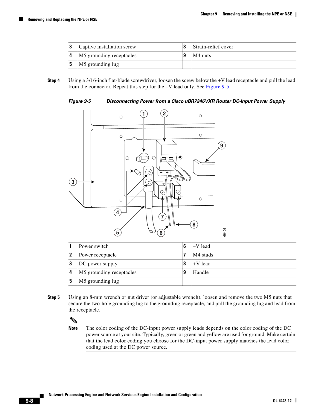
3

Captive installation screw

8

Strain-relief cover


4

M5 grounding receptacles

9

M4 nuts


5

M5 grounding lug


Step 4 Using a 3/16-inch flat-blade screwdriver, loosen the screw below the +V lead receptacle and pull the lead from the connector. Repeat this step for the –V lead only. See Figure 9-5.

Figure 9-5 Disconnecting Power from a Cisco uBR7246VXR Router DC-Input Power Supply

1 2

9

3

4

7

8

5

6

66406

1

Power switch

6

–V lead


2

Power receptacle

7

M4 studs


3

DC power supply

8

+V lead


4

M5 grounding receptacles

9

Handle


5

M5 grounding lug


Step 5 Using an 8-mm wrench or nut driver (or adjustable wrench), loosen and remove the two M5 nuts that secure the two-hole grounding lug to the grounding receptacle, and pull the grounding lug and lead from the receptacle.

Note The color coding of the DC-input power supply leads depends on the color coding of the DC power source at your site. Typically, green or green and yellow are used for ground. Make certain that the lead color coding you choose for the DC-input power supply matches the lead color coding used at the DC power source.

Network Processing Engine and Network Services Engine Installation and Configuration

9-8

OL-4448-12


Page 178
Image 178
Cisco Systems NPE-225, NPE-175 manual 66406