Chapter 7
Installing the
Figure 7-20 Installing the Rear Cable-Management Brackets with the NPE-G1 or NPE-G2—Router Rear-Mounted
![]()
![]()
![]() 1
1 ![]()
G I G A B I T | E T H E R N E T 0 / 1 |
|
| G I G A B I T | E T H E R N E T 0 / 1 |
| G I G A B I T | E T H E R N E T 0 / 1 |
| NETWORK PROCESSING ENGINE |
|
| 1S L O T |
|
| |||
L I N K |
|
|
|
|
|
| - | G1 |
|
| ||||||||
|
|
|
| L I N K |
|
|
| L I N K |
|
|
|
|
| |||||
|
|
|
|
|
|
|
|
|
|
|
|
| C P U |
|
| A C T I V E |
|
|
|
|
|
|
|
|
|
|
|
|
|
|
| R E S E T |
|
|
|
|
|
E N | R X | G B I C | T X |
| E N |
|
|
| E N |
|
|
|
|
|
|
|
|
|
R J 4 5 | R J 4 5 |
| R X | G B I C | T X |
|
|
|
|
|
|
|
|
| ||||
|
|
|
|
| R J 4 5 | R X | G B I C | T X | C O M PA C T F L A S H |
|
| POWER | CONSOLE | AUX | ||||
|
|
|
|
|
|
|
|
|
|
|
|
|
|
| ON | |||
66750
1
Screws
Step 1 Align the
Step 2 Insert and tighten two screws for each bracket. The screws come with the
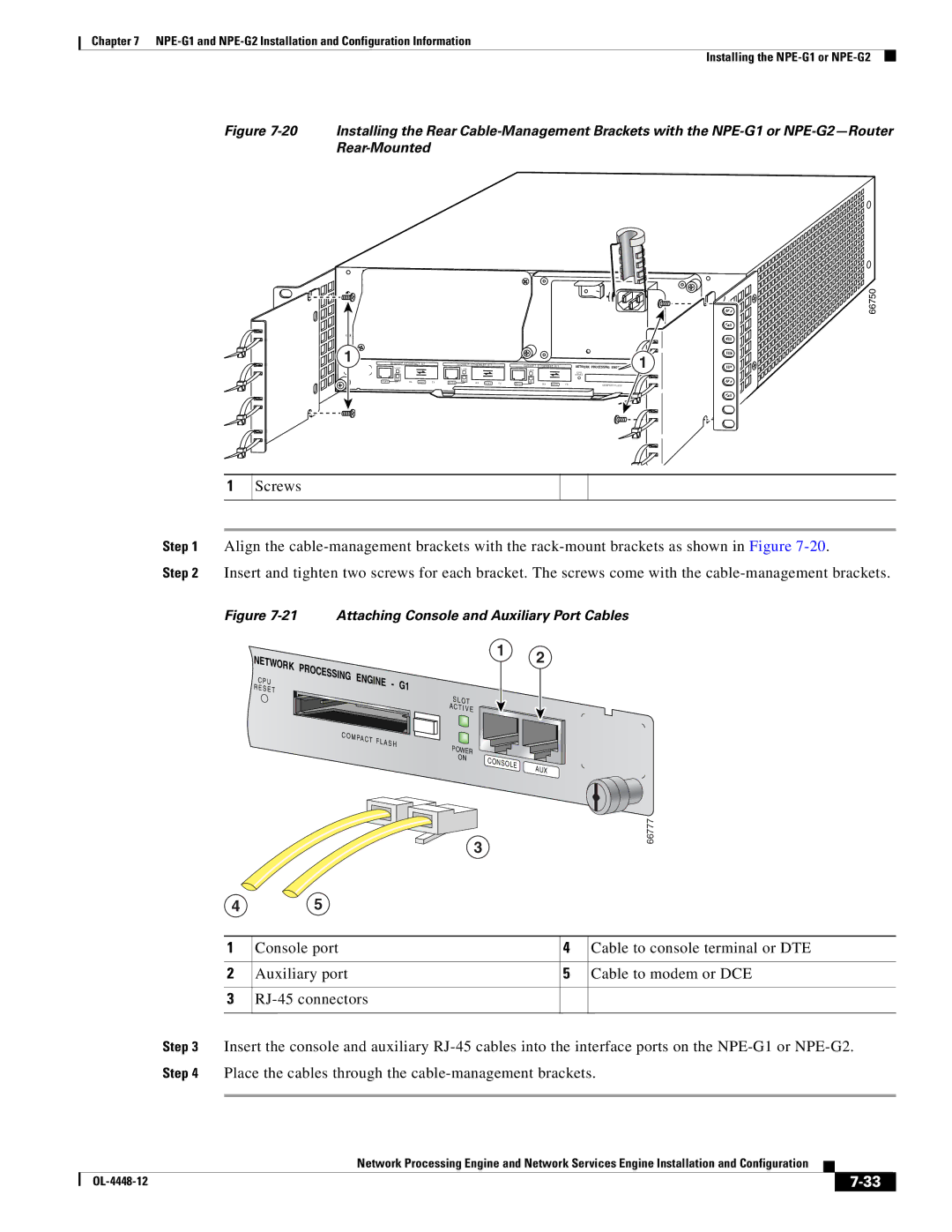
Figure 7-21 Attaching Console and Auxiliary Port Cables
NETWORK
C P U
R E S E T
PROCESSING | ENGINE | - | G1 |
| |||
|
|
| |
|
|
| S L OT |
|
|
| A |
|
|
| C T I V E |
C O M |
|
| |
| PAC T |
|
|
| F L A S H | POWER | |
|
|
| |
|
|
| ON |
1 2
CONSOLE | AUX |
|
3
45
66777
1 | Console port | 4 | Cable to console terminal or DTE |
|
|
|
|
2 | Auxiliary port | 5 | Cable to modem or DCE |
|
|
|
|
3 |
|
| |
|
|
|
|
Step 3 Insert the console and auxiliary
Network Processing Engine and Network Services Engine Installation and Configuration
|
| ||
|
|