Chapter 6
•The port numbering for the interfaces on the
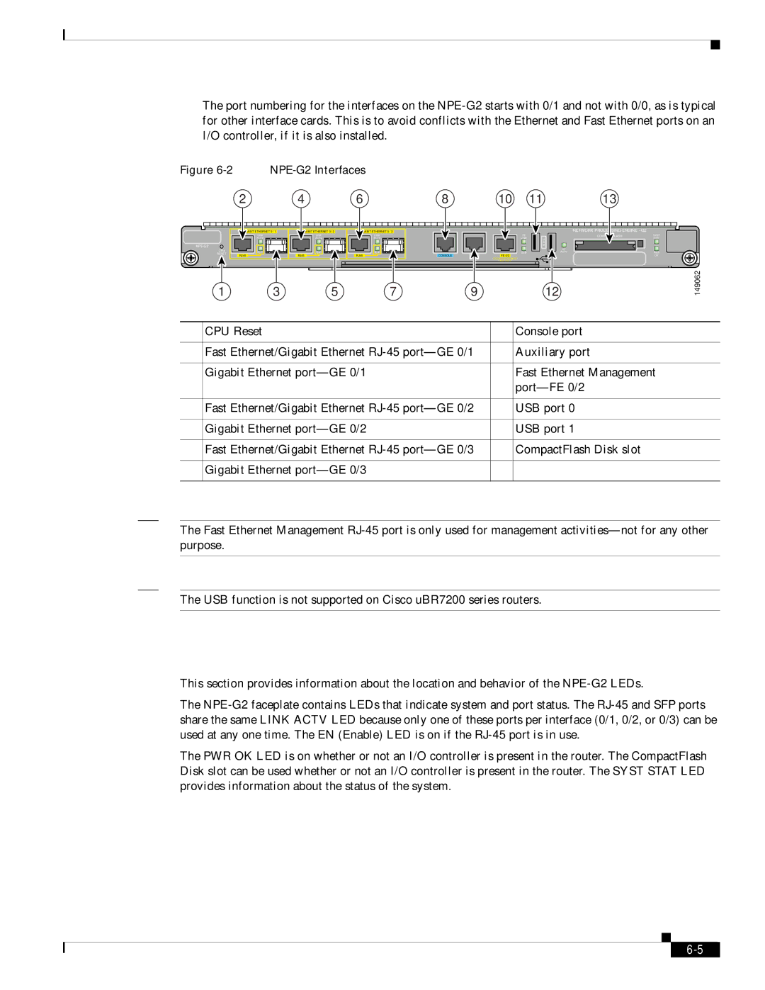
Figure 6-2 NPE-G2 Interfaces
2 | 4 | 6 | 8 | 10 | 11 | 13 |
| ETHERNET 0 / 1 | ETHERNET 0 / 2 | ETHERNET 0 / 2 |
|
|
| NETWORK PROCESSING ENGINE - G2 |
|
| LINK | LINK | LINK |
| FE |
| FLASH | SYST |
| ACTV | ACTV | ACTV |
| LINK | U |
| STAT |
|
|
|
|
|
| S |
|
|
|
|
|
|
| B |
|
| |
CPU |
|
|
|
|
| CF |
|
|
EN | EN | EN |
| USB | ACTV |
| PWR | |
RESET |
|
| ||||||
| RJ45 | RJ45 | RJ45 | CONSOLE | FE 0/2 |
|
| OK |
|
|
|
|
| FOR MANAGEMENT |
|
|
|
|
|
|
|
| USE ONLY |
|
|
|
1 | 3 | 5 | 7 | 9 |
| 12 |
| 149062 |
1 | CPU Reset | 8 | Console port |
|
|
|
|
2 | Fast Ethernet/Gigabit Ethernet | 9 | Auxiliary port |
|
|
|
|
3 | Gigabit Ethernet | 10 | Fast Ethernet Management |
|
|
| |
|
|
|
|
4 | Fast Ethernet/Gigabit Ethernet | 11 | USB port 0 |
|
|
|
|
5 | Gigabit Ethernet | 12 | USB port 1 |
|
|
|
|
6 | Fast Ethernet/Gigabit Ethernet | 13 | CompactFlash Disk slot |
|
|
|
|
7 | Gigabit Ethernet |
|
|
|
|
|
|
Note The Fast Ethernet Management
Note The USB function is not supported on Cisco uBR7200 series routers.
LEDs
This section provides information about the location and behavior of the
The
The PWR OK LED is on whether or not an I/O controller is present in the router. The CompactFlash Disk slot can be used whether or not an I/O controller is present in the router. The SYST STAT LED provides information about the status of the system.
Network Processing Engine and Network Services Engine Installation and Configuration
|
| ||
|
|