Chapter 7
Installing the
Reconnecting AC-Input Power to the Cisco uBR7225VXR Router
To connect
Step 1 At the rear of the router, ensure that the power switch on the power supply is in the off position.
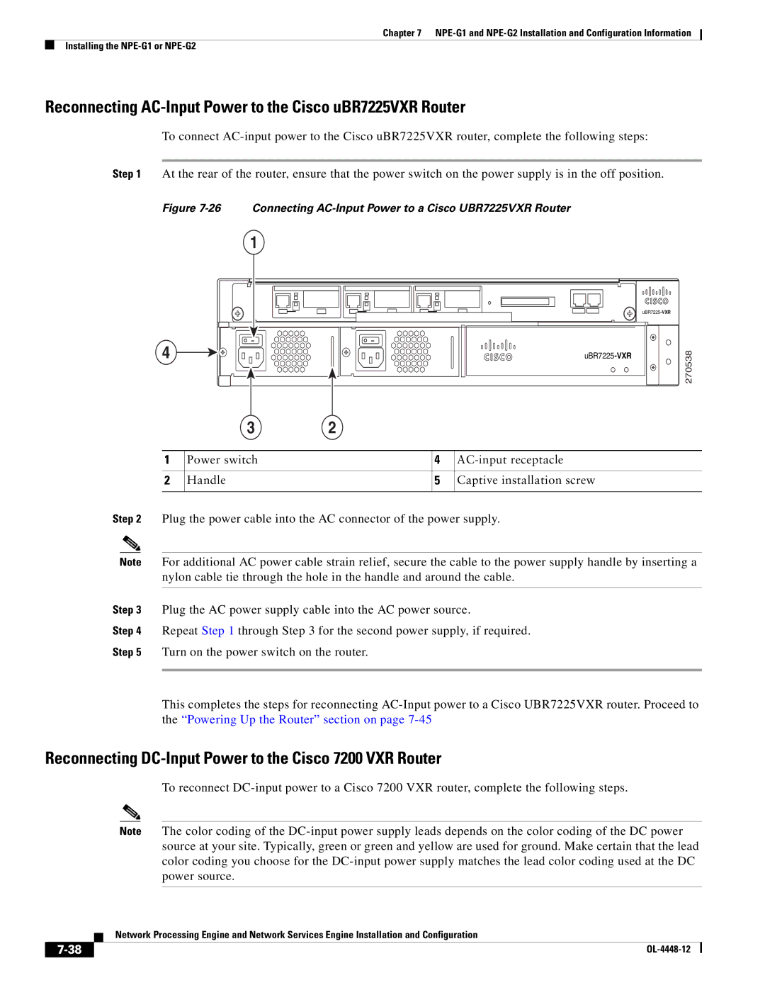
Figure 7-26 Connecting AC-Input Power to a Cisco UBR7225VXR Router
| 1 |
|
|
| |
4 | 38 | |
|
| 2705 |
| 3 | 2 |
|
|
|
|
|
|
|
1 | Power switch |
| 4 | |
|
|
|
|
|
2 | Handle |
| 5 | Captive installation screw |
|
|
|
|
|
Step 2 Plug the power cable into the AC connector of the power supply.
Note For additional AC power cable strain relief, secure the cable to the power supply handle by inserting a nylon cable tie through the hole in the handle and around the cable.
Step 3 Plug the AC power supply cable into the AC power source.
Step 4 Repeat Step 1 through Step 3 for the second power supply, if required.
Step 5 Turn on the power switch on the router.
This completes the steps for reconnecting
Reconnecting DC-Input Power to the Cisco 7200 VXR Router
To reconnect
Note The color coding of the
Network Processing Engine and Network Services Engine Installation and Configuration
|
| |
|