Chapter 5
•Only one port per interface can be used at any one time. For example, for interface Gigabit Ethernet 0/1, either the
•A total of three ports on any of the three interfaces (0/1, 0/2, or 0/3) can be used at any one time; for example, 0/1 GBIC, 0/2 GBIC, and 0/3
•The port numbering for the interfaces on the
Figure |
1
G I G | I T | E T H E |
|
|
|
|
| ||
|
|
|
| |
L I | N K | R N E T | 0 | / 3 |
|
|
|
|
| NETWORK | PROCESSING | ENGINE |
|
|
| |
|
|
|
| C P U | - | G1 |
| |||
R J 4 5 | E N |
|
| R E | S E T |
|
|
|
| |
|
|
|
|
|
|
| S L OT | |||
|
| R X |
|
|
|
|
|
| A | |
|
| G B I C |
|
|
|
|
| C T I V E | ||
|
|
| T X |
|
|
|
| |||
|
|
|
|
|
|
|
| |||
|
|
|
|
|
|
|
|
|
| |
|
|
|
|
|
| C O M |
|
|
| |
|
|
|
|
|
|
| PAC T |
|
|
|
|
|
|
|
|
|
| F L A S H | POWER | ||
| 2 |
|
|
|
|
|
|
| ||
|
|
|
|
|
|
|
|
| ON | |
|
|
|
|
|
|
|
|
|
| |
4
3
CONSOLE | AUX |
|
|
|
|
| 66873 |
|
|
|
|
|
|
|
|
|
|
|
| LED flashes when |
No. | LED Label | LED | Color | In the Power Up state, the LED is | there is traffic |
|
|
|
|
|
|
1 | LINK (Interfaces 0/1, 0/2, | Green | On, indicating that a link has been | No | |
| 0/3) |
|
| established |
|
|
|
|
|
|
|
2 | EN (Enable) (Interfaces | Green | On if the | — | |
| 0/1, 0/2, 0/3) |
|
| Off if the GBIC port is selected |
|
|
|
|
|
| |
|
|
|
|
|
|
3 | SLOT ACTIVE | CompactFlash Disk | Green | On when the slot is being used | — |
|
|
|
|
|
|
4 | POWER ON | Power | Green | On and stays on | No |
|
|
|
|
|
|
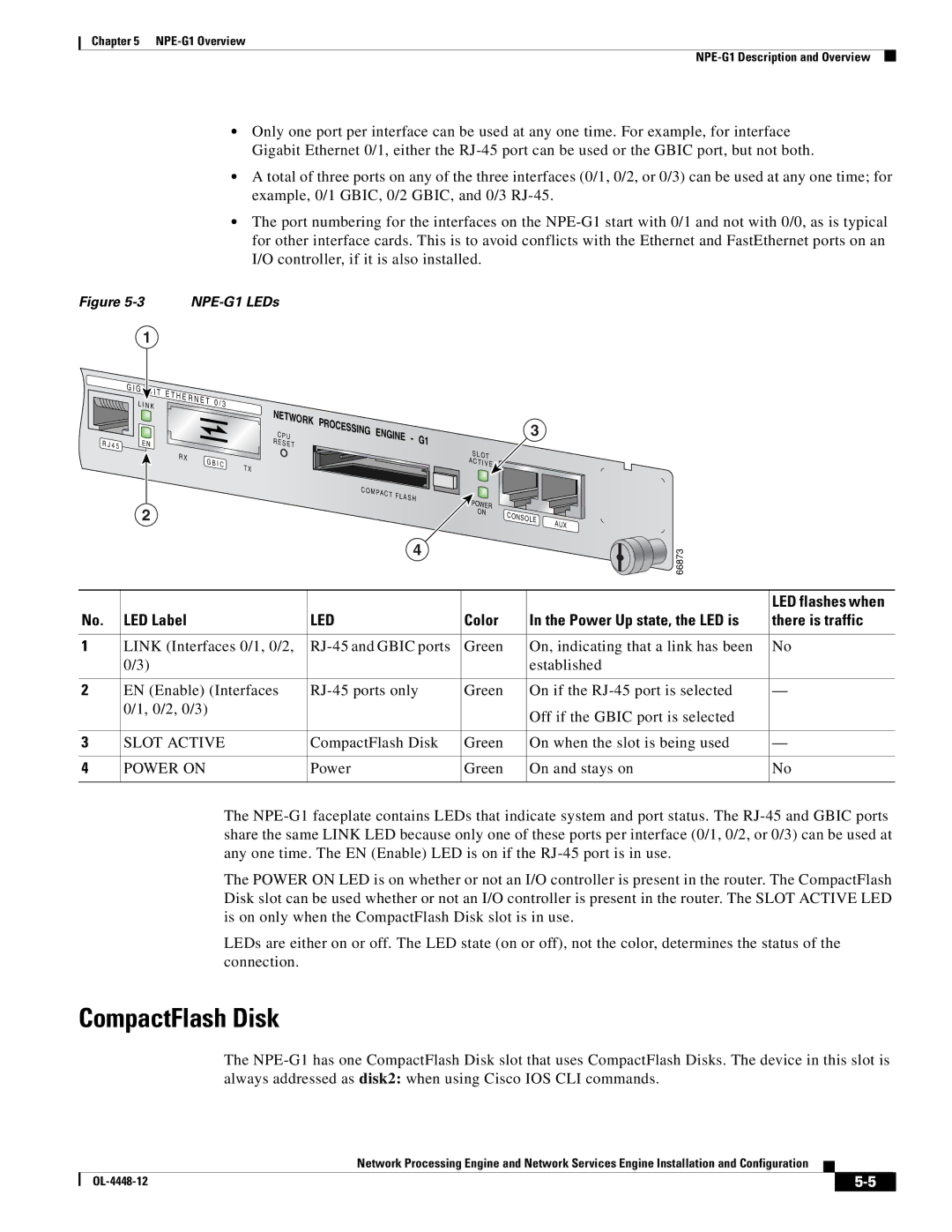
The
The POWER ON LED is on whether or not an I/O controller is present in the router. The CompactFlash Disk slot can be used whether or not an I/O controller is present in the router. The SLOT ACTIVE LED is on only when the CompactFlash Disk slot is in use.
LEDs are either on or off. The LED state (on or off), not the color, determines the status of the connection.
CompactFlash Disk
The
Network Processing Engine and Network Services Engine Installation and Configuration
|
| ||
|
|
