Chapter 7
Installing the
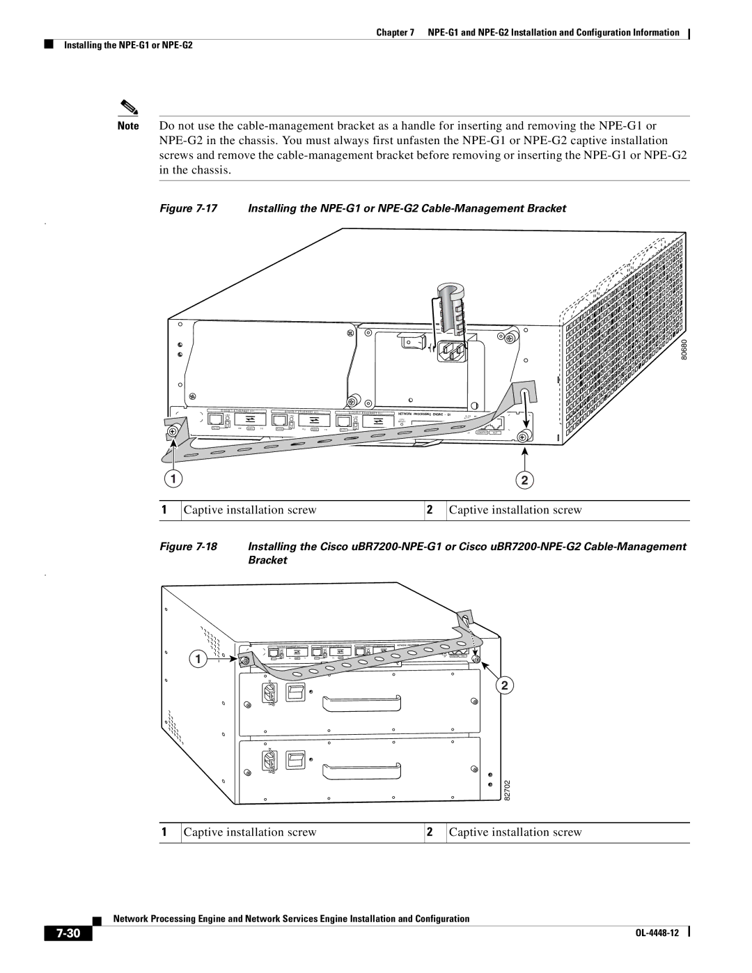
Note Do not use the
Figure 7-17 Installing the NPE-G1 or NPE-G2 Cable-Management Bracket
.
G I G A B I T | E T H E R N E T 0 / 1 |
| G I G A B I T | E T H E R N E T 0 / 1 |
|
| G I G A B I T | E T H E R N E T 0 / 1 |
| NETWORK PROCESSING ENGINE |
|
| |||
L I N K |
|
|
|
|
|
| - | 1 | |||||||
|
|
| L I N K |
|
|
|
| L I N K |
|
|
| ||||
|
|
|
|
|
|
|
|
|
|
| C P U |
|
| ||
|
|
|
|
|
|
|
|
|
|
|
|
|
|
| |
|
|
|
|
|
|
|
|
|
|
|
|
| R E S E T |
|
|
E N |
|
|
| E N |
|
|
|
|
|
|
|
|
|
|
|
R J 4 5 | R X | G B I C | T X | R J 4 5 | R X | G B I C | T X | R J 4 5 | E N | R X | G B I C | T X | C O M PA C T F L A S H |
| |
|
|
|
|
|
|
|
|
|
| ||||||
S L O T A C T I V E
POWER OK
80680
CONSOLE | AUX |
1 | 2 |
1
Captive installation screw
2
Captive installation screw
Figure 7-18 Installing the Cisco uBR7200-NPE-G1 or Cisco uBR7200-NPE-G2 Cable-Management Bracket
.
1
| G I G A B I T | E T H E R N E T 0 / 1 |
| G I G A B I T | E T H E R N E T 0 / 1 |
| G I G A B I T | E T H E R N E T 0 / 1 |
| NETWORK PROCESSING ENGINE | - | G1 | |||
| L I N K |
|
|
| L I N K |
|
|
| L I N K |
|
|
| C P U |
|
|
|
|
|
|
|
|
|
|
|
|
|
| R E S E T |
|
| |
| E N |
|
|
| E N |
|
|
| E N | R X | G B I C | T X | C O M PA C T F L A S H |
|
|
R J 4 5 | R X | G B I C | T X | R J 4 5 | R X | G B I C | T X | R J 4 5 |
|
|
| ||||
S L O T |
|
|
A C T I V E |
|
|
POWER | CONSOLE | AUX |
ON |
2
82702
1
Captive installation screw
2
Captive installation screw
Network Processing Engine and Network Services Engine Installation and Configuration
|
| |
|