Chapter 7
Installing the
Step 5 If the SODIMM appears misaligned, carefully remove it and reseat it in the socket. Push the SODIMM gently back into the socket until the spring latches snap into place.
You have finished replacing the SDRAM SODIMM. To install the
Inserting the NPE-G1 or NPE-G2 into the Router
Note If you have difficulty installing a network processing engine or I/O controller in the lowest slot of a Cisco 7200 VXR router that is
To insert the
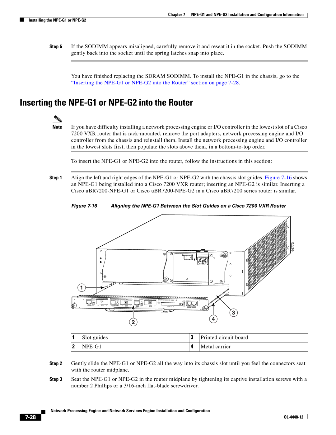
Step 1 Align the left and right edges of the
Figure 7-16 Aligning the NPE-G1 Between the Slot Guides on a Cisco 7200 VXR Router
 66773
66773
1
G I G A B I T | E T H E R N E T 0 / 1 |
| G I G A B I T | E T H E R N E T 0 / 1 |
|
| G I G A B I T | E T H E R N E T 0 / 1 |
| NETWORK PROCESSING ENGINE |
|
| |||
L I N K |
|
|
|
|
|
| - | G1 | |||||||
|
|
|
| L I N K |
|
|
|
| L I N K |
|
|
| C P U |
|
|
|
|
|
|
|
|
|
|
|
|
|
|
|
|
| |
|
|
|
|
|
|
|
|
|
|
|
|
| R E S E T |
|
|
E N |
|
|
| E N |
|
|
|
|
|
|
|
|
|
|
|
R J 4 5 | R X | G B I C | T X | R J 4 5 | R X | G B I C | T X | R J 4 5 | E N | R X | G B I C | T X | C O M PA C T F L A S H |
|
|
|
|
|
|
|
|
|
|
|
|
| |||||
2
S L O T |
|
|
A C T I V E |
|
|
POWER | CONSOLE |
|
ON | AUX |
3
4
1 | Slot guides | 3 | Printed circuit board |
|
|
|
|
2 |
| 4 | Metal carrier |
|
|
|
|
Step 2 Gently slide the
Step 3 Seat the
Network Processing Engine and Network Services Engine Installation and Configuration
|
| |
|