Chapter 7
Removing the Network Processing Engine
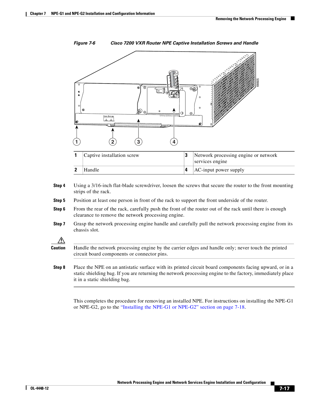
Figure 7-6 Cisco 7200 VXR Router NPE Captive Installation Screws and Handle
66605
1 | 2 | 3 | 4 |
|
|
|
|
|
|
| |
1 | Captive installation screw |
| 3 | Network processing engine or network | |
|
|
|
|
| services engine |
|
|
|
|
|
|
2 | Handle |
|
| 4 | |
|
|
|
|
|
|
Step 4 Using a
Step 5 Position at least one person in front of the rack to support the front underside of the router.
Step 6 From the rear of the rack, carefully push the front of the router out of the rack until there is enough clearance to remove the network processing engine.
Step 7 Grasp the network processing engine handle and carefully pull the network processing engine from its chassis slot.
Caution Handle the network processing engine by the carrier edges and handle only; never touch the printed circuit board components or connector pins.
Step 8 Place the NPE on an antistatic surface with its printed circuit board components facing upward, or in a static shielding bag. If you are returning the network processing engine to the factory, immediately place it in a static shielding bag.
This completes the procedure for removing an installed NPE. For instructions on installing the
Network Processing Engine and Network Services Engine Installation and Configuration
|
| ||
|
|