Chapter 6 NPE-G2 Overview

NPE-G2 Memory Information and Specifications

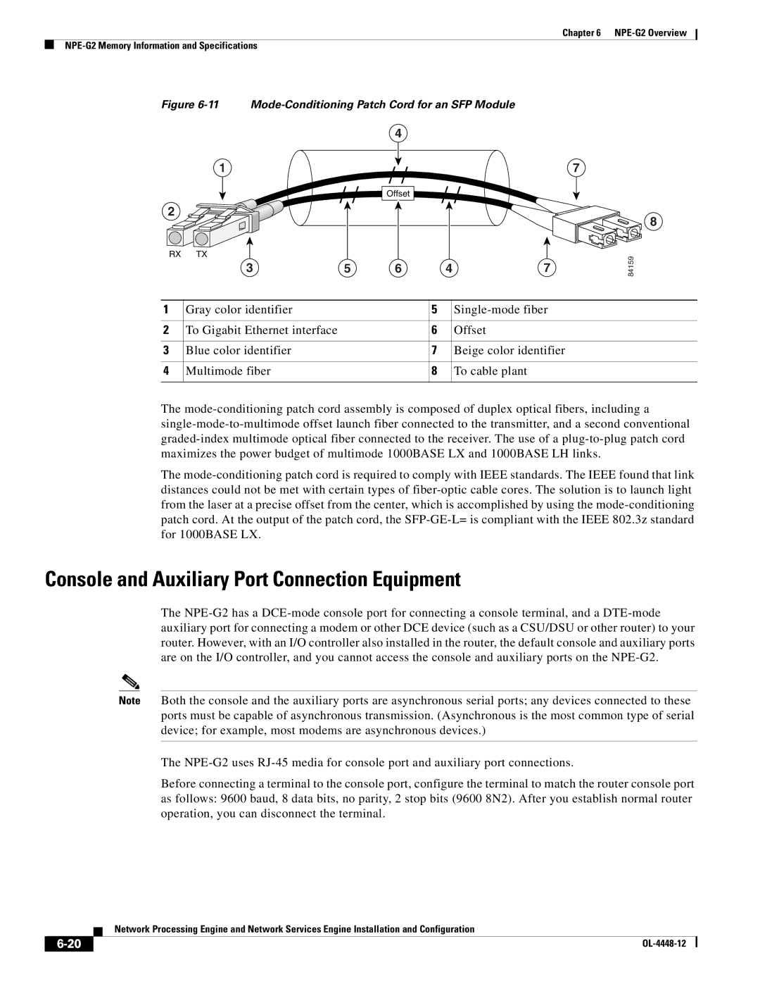
Figure 6-11 Mode-Conditioning Patch Cord for an SFP Module


4


1

/ /

7

/ /

/ /

Offset


2

RX TX

3

5

6

4

7

8

84159

1

Gray color identifier

5

Single-mode fiber


2

To Gigabit Ethernet interface

6

Offset


3

Blue color identifier

7

Beige color identifier


4

Multimode fiber

8

To cable plant


The mode-conditioning patch cord assembly is composed of duplex optical fibers, including a single-mode-to-multimode offset launch fiber connected to the transmitter, and a second conventional graded-index multimode optical fiber connected to the receiver. The use of a plug-to-plug patch cord maximizes the power budget of multimode 1000BASE LX and 1000BASE LH links.

The mode-conditioning patch cord is required to comply with IEEE standards. The IEEE found that link distances could not be met with certain types of fiber-optic cable cores. The solution is to launch light from the laser at a precise offset from the center, which is accomplished by using the mode-conditioning patch cord. At the output of the patch cord, the SFP-GE-L= is compliant with the IEEE 802.3z standard for 1000BASE LX.

Console and Auxiliary Port Connection Equipment

The NPE-G2 has a DCE-mode console port for connecting a console terminal, and a DTE-mode auxiliary port for connecting a modem or other DCE device (such as a CSU/DSU or other router) to your router. However, with an I/O controller also installed in the router, the default console and auxiliary ports are on the I/O controller, and you cannot access the console and auxiliary ports on the NPE-G2.

Note Both the console and the auxiliary ports are asynchronous serial ports; any devices connected to these ports must be capable of asynchronous transmission. (Asynchronous is the most common type of serial device; for example, most modems are asynchronous devices.)

The NPE-G2 uses RJ-45 media for console port and auxiliary port connections.

Before connecting a terminal to the console port, configure the terminal to match the router console port as follows: 9600 baud, 8 data bits, no parity, 2 stop bits (9600 8N2). After you establish normal router operation, you can disconnect the terminal.

Network Processing Engine and Network Services Engine Installation and Configuration

6-20

OL-4448-12


Page 82
Image 82
Cisco Systems NPE-225, NPE-175 manual Mode-Conditioning Patch Cord for an SFP Module